8 TROUBLESHOOTING

MELSEC-Q

8 TROUBLESHOOTING

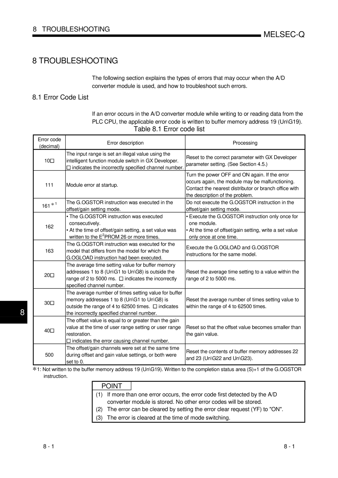
The following section explains the types of errors that may occur when the A/D converter module is used, and how to troubleshoot such errors.

8.1 Error Code List

If an error occurs in the A/D converter module while writing to or reading data from the

PLC CPU, the applicable error code is written to buffer memory address 19 (Un\G19).

Table 8.1 Error code list


Error code

Error description

Processing


(decimal)


The input range is set an illegal value using the

Reset to the correct parameter with GX Developer


10

intelligent function module switch in GX Developer.


parameter setting. (See Section 4.5.)


indicates the incorrectly specified channel number.


Turn the power OFF and ON again. If the error


111

Module error at startup.

occurs again, the module may be malfunctioning.


Contact the nearest distributor or branch office with


the description of the problem.


161 1

The G.OGSTOR instruction was executed in the

Do not execute the G.OGSTOR instruction in the


offset/gain setting mode.

offset/gain setting mode.


• The G.OGSTOR instruction was executed

• Execute the G.OGSTOR instruction only once for


162

consecutively.

one module.


• At the time of offset/gain setting, a set value was

• At the time of offset/gain setting, write a set value


written to the E2PROM 26 or more times.

only once at one time.


The G.OGSTOR instruction was executed for the

Execute the G.OGLOAD and G.OGSTOR


163

model that differs from the model for which the


instructions for the same model.


G.OGLOAD instruction had been executed.


The average time setting value for buffer memory


20

addresses 1 to 8 (Un\G1 to Un\G8) is outside the

Reset the average time setting to a value within the


range of 2 to 5000 ms. indicates the incorrectly

range of 2 to 5000 ms.


specified channel number.


The average number of times setting value for buffer


30

memory addresses 1 to 8 (Un\G1 to Un\G8) is

Reset the average number of times setting value to


outside the range of 4 to 62500 times. indicates

within the range of 4 to 62500 times.

8


the incorrectly specified channel number.


The offset value is equal to or greater than the gain


40

value at the time of user range setting or user range

Reset so that the offset value becomes smaller than


restoration.

the gain value.


indicates the error causing channel number.


The offset/gain channels were set at the same time

Reset the contents of buffer memory addresses 22


500

during offset and gain value settings, or both were


and 23 (Un\G22 and Un\G23).


set to 0.


1: Not written to the buffer memory address 19 (Un\G19). Written to the completion status area (S)+1 of the G.OGSTOR instruction.

POINT

(1)If more than one error occurs, the error code first detected by the A/D converter module is stored. No other error codes will be stored.

(2)The error can be cleared by setting the error clear request (YF) to "ON".

(3)The error is cleared at the time of mode switching.

8 - 1

8 - 1

Page 115
Image 115
Mitsubishi Electronics Q68ADV, Q68ADI, Q64AD user manual Error Code List

Q68ADV, Q68ADI, Q64AD specifications

Mitsubishi Electronics, a renowned leader in automation technology, has developed advanced analog input modules that play a crucial role in numerous industrial applications. Among them, the Q64AD, Q68ADI, and Q68ADV models stand out with their impressive features and capabilities tailored for precise data acquisition and control.

The Q64AD module is designed for high-performance analog signal processing. It offers up to 16 channels of differential input, making it suitable for applications requiring multiple sensor readings simultaneously. The resolution of 16 bits enables accurate data capture, ensuring that subtle variations in process variables, such as temperature or pressure, are detectable. One of its key advantages is the high-speed sampling capability, allowing data collection at rates of up to 100 milliseconds per channel, essential for real-time monitoring in fast-paced environments.

In contrast, the Q68ADI model enhances the versatility of the analog input system. It includes built-in isolators, providing additional protection against noise and interference commonly found in industrial settings. This isolation feature improves the reliability of sensor readings, especially in harsh environments where electrical noise can impact performance. Furthermore, the Q68ADI supports both voltage and current input types, making it adaptable to various sensor configurations, such as thermocouples and RTDs, expanding its usability across different applications.

The Q68ADV module takes versatility a step further by integrating advanced diagnostic features. This model offers a range of additional functions, including built-in fault detection and self-diagnosis capabilities that identify issues before they escalate into significant problems. It also features temperature compensation and linearization algorithms, which enhance the accuracy of reading from thermocouples and other temperature sensors. The Q68ADV module is ideal for applications demanding high reliability and stringent performance standards, making it indispensable in industries like pharmaceuticals and food processing.

All three models are designed to seamlessly integrate with Mitsubishi's PLC systems, ensuring smooth communication and data exchange. They support various protocols, making them compatible with a wide range of devices and systems. Collectively, the Q64AD, Q68ADI, and Q68ADV modules exemplify Mitsubishi Electronics' commitment to delivering high-quality, reliable, and innovative solutions in industrial automation, empowering businesses to achieve greater efficiency and operational excellence.