3 SPECIFICATIONS

3.4.3 Buffer memory assignment (Q68ADI)

MELSEC-Q

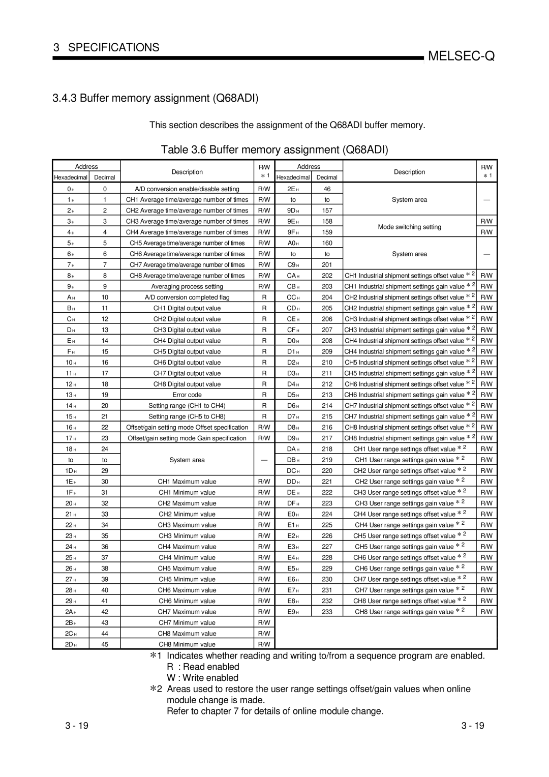
This section describes the assignment of the Q68ADI buffer memory.

Table 3.6 Buffer memory assignment (Q68ADI)

Address

Description

R/W

Address


Description


R/W

Hexadecimal

Decimal

1

Hexadecimal

Decimal


1


0 H

0

A/D conversion enable/disable setting

R/W

2E H


46


1 H

1

CH1 Average time/average number of times

R/W

to


to

System area


2 H

2

CH2 Average time/average number of times

R/W

9D H


157


3 H

3

CH3 Average time/average number of times

R/W

9E H


158

Mode switching setting


R/W

4 H

4

CH4 Average time/average number of times

R/W

9F H


159


R/W


5 H

5

CH5 Average time/average number of times

R/W

A0 H


160


6 H

6

CH6 Average time/average number of times

R/W

to


to

System area


7 H

7

CH7 Average time/average number of times

R/W

C9 H


201


8 H

8

CH8 Average time/average number of times

R/W

CA H


202

CH1 Industrial shipment settings offset value

2

R/W

9 H

9

Averaging process setting

R/W

CB H


203

CH1 Industrial shipment settings gain value

2

R/W

A H

10

A/D conversion completed flag

R

CC H


204

CH2 Industrial shipment settings offset value

2

R/W

B H

11

CH1 Digital output value

R

CD H


205

CH2 Industrial shipment settings gain value

2

R/W

C H

12

CH2 Digital output value

R

CE H


206

CH3 Industrial shipment settings offset value

2

R/W

D H

13

CH3 Digital output value

R

CF H


207

CH3 Industrial shipment settings gain value

2

R/W

E H

14

CH4 Digital output value

R

D0 H


208

CH4 Industrial shipment settings offset value

2

R/W

F H

15

CH5 Digital output value

R

D1 H


209

CH4 Industrial shipment settings gain value

2

R/W

10 H

16

CH6 Digital output value

R

D2 H


210

CH5 Industrial shipment settings offset value

2

R/W

11 H

17

CH7 Digital output value

R

D3 H


211

CH5 Industrial shipment settings gain value

2

R/W

12 H

18

CH8 Digital output value

R

D4 H


212

CH6 Industrial shipment settings offset value

2

R/W

13 H

19

Error code

R

D5 H


213

CH6 Industrial shipment settings gain value

2

R/W

14 H

20

Setting range (CH1 to CH4)

R

D6 H


214

CH7 Industrial shipment settings offset value

2

R/W

15 H

21

Setting range (CH5 to CH8)

R

D7 H


215

CH7 Industrial shipment settings gain value

2

R/W

16 H

22

Offset/gain setting mode Offset specification

R/W

D8 H


216

CH8 Industrial shipment settings offset value

2

R/W

17 H

23

Offset/gain setting mode Gain specification

R/W

D9 H


217

CH8 Industrial shipment settings gain value

2

R/W

18 H

24


DA H


218

CH1 User range settings offset value

2


R/W

to

to

System area

DB H


219

CH1 User range settings gain value

2


R/W

1D H

29


DC H


220

CH2 User range settings offset value

2


R/W

1E H

30

CH1 Maximum value

R/W

DD H


221

CH2 User range settings gain value

2


R/W

1F H

31

CH1 Minimum value

R/W

DE H


222

CH3 User range settings offset value

2


R/W

20 H

32

CH2 Maximum value

R/W

DF H


223

CH3 User range settings gain value

2


R/W

21 H

33

CH2 Minimum value

R/W

E0 H


224

CH4 User range settings offset value

2


R/W

22 H

34

CH3 Maximum value

R/W

E1 H


225

CH4 User range settings gain value

2


R/W

23 H

35

CH3 Minimum value

R/W

E2 H


226

CH5 User range settings offset value

2


R/W

24 H

36

CH4 Maximum value

R/W

E3 H


227

CH5 User range settings gain value

2


R/W

25 H

37

CH4 Minimum value

R/W

E4 H


228

CH6 User range settings offset value

2


R/W

26 H

38

CH5 Maximum value

R/W

E5 H


229

CH6 User range settings gain value

2


R/W

27 H

39

CH5 Minimum value

R/W

E6 H


230

CH7 User range settings offset value

2


R/W

28 H

40

CH6 Maximum value

R/W

E7 H


231

CH7 User range settings gain value

2


R/W

29 H

41

CH6 Minimum value

R/W

E8 H


232

CH8 User range settings offset value

2


R/W

2A H

42

CH7 Maximum value

R/W

E9 H


233

CH8 User range settings gain value

2


R/W

2B H

43

CH7 Minimum value

R/W


2C H

44

CH8 Maximum value

R/W


2D H

45

CH8 Minimum value

R/W


1 Indicates whether reading and writing to/from a sequence program are enabled.

R: Read enabled W : Write enabled

2 Areas used to restore the user range settings offset/gain values when online module change is made.

Refer to chapter 7 for details of online module change.

3 - 19

3 - 19

Page 36
Image 36
Mitsubishi Electronics Q68ADV, Q64AD user manual Buffer memory assignment Q68ADI

Q68ADV, Q68ADI, Q64AD specifications

Mitsubishi Electronics, a renowned leader in automation technology, has developed advanced analog input modules that play a crucial role in numerous industrial applications. Among them, the Q64AD, Q68ADI, and Q68ADV models stand out with their impressive features and capabilities tailored for precise data acquisition and control.

The Q64AD module is designed for high-performance analog signal processing. It offers up to 16 channels of differential input, making it suitable for applications requiring multiple sensor readings simultaneously. The resolution of 16 bits enables accurate data capture, ensuring that subtle variations in process variables, such as temperature or pressure, are detectable. One of its key advantages is the high-speed sampling capability, allowing data collection at rates of up to 100 milliseconds per channel, essential for real-time monitoring in fast-paced environments.

In contrast, the Q68ADI model enhances the versatility of the analog input system. It includes built-in isolators, providing additional protection against noise and interference commonly found in industrial settings. This isolation feature improves the reliability of sensor readings, especially in harsh environments where electrical noise can impact performance. Furthermore, the Q68ADI supports both voltage and current input types, making it adaptable to various sensor configurations, such as thermocouples and RTDs, expanding its usability across different applications.

The Q68ADV module takes versatility a step further by integrating advanced diagnostic features. This model offers a range of additional functions, including built-in fault detection and self-diagnosis capabilities that identify issues before they escalate into significant problems. It also features temperature compensation and linearization algorithms, which enhance the accuracy of reading from thermocouples and other temperature sensors. The Q68ADV module is ideal for applications demanding high reliability and stringent performance standards, making it indispensable in industries like pharmaceuticals and food processing.

All three models are designed to seamlessly integrate with Mitsubishi's PLC systems, ensuring smooth communication and data exchange. They support various protocols, making them compatible with a wide range of devices and systems. Collectively, the Q64AD, Q68ADI, and Q68ADV modules exemplify Mitsubishi Electronics' commitment to delivering high-quality, reliable, and innovative solutions in industrial automation, empowering businesses to achieve greater efficiency and operational excellence.