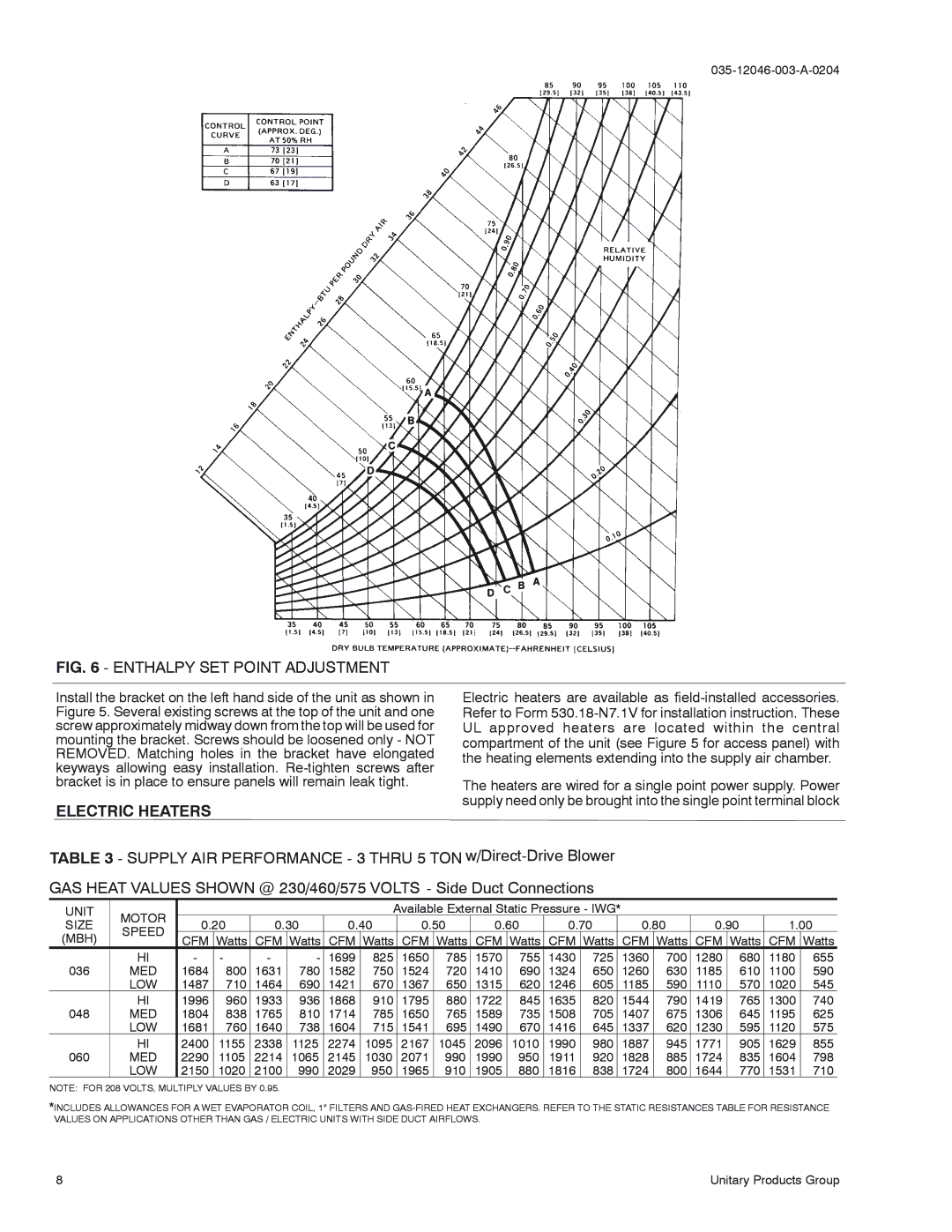
D2EE 036, D1EE 060, D1EE 048 specifications
The York D1EE 048, D2EE 036, and D1EE 060 are advanced air conditioning units designed for superior performance and energy efficiency in commercial and industrial environments. These models are part of York’s reputation for creating reliable HVAC systems that cater to a variety of applications.The York D1EE 048 is a high-efficiency rooftop unit, renowned for its compact design and robust construction. This model boasts an integrated economizer that enhances energy savings by optimizing the use of outside air for cooling. It features a cutting-edge variable speed compressor, which provides precision cooling and reduces energy consumption under varying load conditions. The advanced microprocessor control system enables quick adjustments to system performance, further enhancing comfort and efficiency.
In contrast, the York D2EE 036 is another exemplary model, distinguished by its dual-stage heating and cooling capabilities. This unit is particularly advantageous for facilities requiring consistent temperature control throughout different seasons. With a SEER rating that meets or exceeds regulatory requirements, the D2EE 036 helps operators minimize downtime and achieve lower operational costs. Its innovative design includes a streamlined airflow system, enabling quiet operation without compromising cooling performance.
Finally, the York D1EE 060 rounds out this trio with its innovative features tailored for large-building applications. This unit is equipped with advanced inverter technology, which allows for seamless adjustments in cooling capacity based on real-time demand. The unit is designed with high-performance heat exchangers that optimize thermal transfer efficiency, ensuring rapid cooling response while maintaining low energy usage. Its smart connectivity features allow for remote monitoring and adjustments, offering facility managers enhanced control over the indoor climate.
In terms of characteristics, all three models prioritize energy efficiency, user-friendly controls, and environmentally responsible refrigerants. They comply with the latest energy standards, making them suitable for organizations aiming for sustainability. With their robust construction and user-centric features, York’s D1EE 048, D2EE 036, and D1EE 060 units represent a commitment to delivering efficient, reliable, and cutting-edge climate control solutions. Whether for small offices or large industrial spaces, these systems provide an optimal balance of performance and cost-effectiveness.

