Field Control Wiring
Wiring Notes:
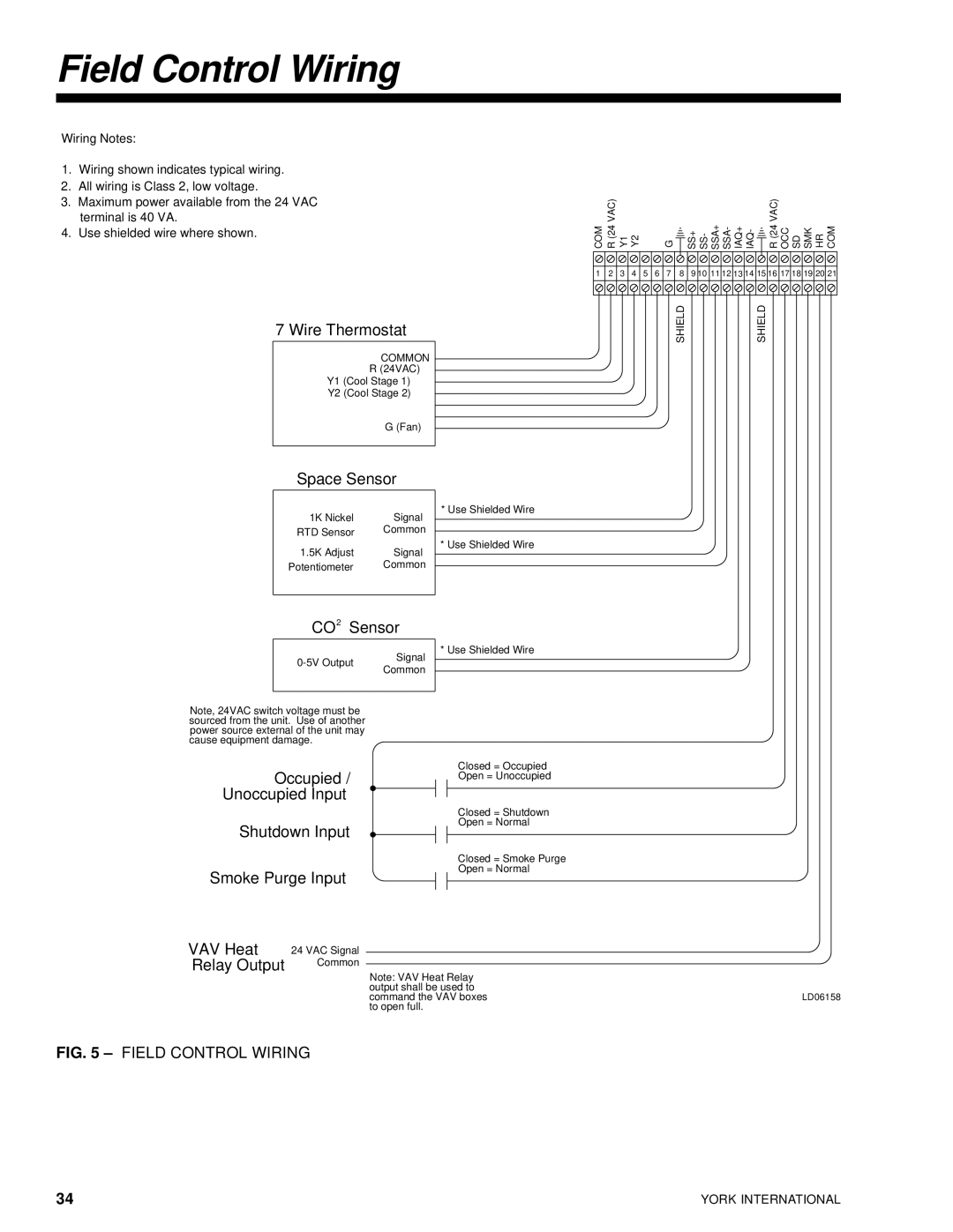
1.Wiring shown indicates typical wiring.
2.All wiring is Class 2, low voltage.
3.Maximum power available from the 24 VAC terminal is 40 VA.
4.Use shielded wire where shown.
7 Wire Thermostat
COMMON
R (24VAC)
Y1 (Cool Stage 1)
Y2 (Cool Stage 2)
| G (Fan) | ||
|
| ||
Space Sensor | |||
|
|
| * Use Shielded Wire |
1K Nickel | Signal |
| |
|
| ||
RTD Sensor | Common |
|
|
1.5K Adjust | Signal |
| * Use Shielded Wire |
|
| ||
Potentiometer | Common |
|
|
|
|
| |
CO2 Sensor | |||
| Signal |
| * Use Shielded Wire |
|
| ||
|
|
| |
Common |
|
| |
|
|
| |
|
|
|
|
COM | R (24 VAC) | Y1 | Y2 |
|
| G |
| SS+ SS- SSA+ SSA- IAQ+ IAQ- | R (24 VAC) | OCC SD SMK HR COM |
1 | 2 | 3 | 4 | 5 | 6 | 7 | 8 | 9 10 11 12 13 14 15 16 | 17 18 19 20 21 | |
|
|
|
|
|
|
| SHIELD |
| SHIELD |
|
Note, 24VAC switch voltage must be sourced from the unit. Use of another power source external of the unit may cause equipment damage.
Occupied /
Unoccupied Input
Shutdown Input
Smoke Purge Input
VAV Heat | 24 VAC Signal |
Relay Output | Common |
Closed = Occupied
Open = Unoccupied
Closed = Shutdown
Open = Normal
Closed = Smoke Purge
Open = Normal
Note: VAV Heat Relay output shall be used to
command the VAV boxesLD06158 to open full.
FIG. 5 – FIELD CONTROL WIRING
34 | YORK INTERNATIONAL |