528194-YTG-F-1210

Airflow Performance

ZF078-150 Side Duct Application

ZF078 (6.5 Ton) Side Duct

Air Flow


Available External Static Pressure - IWG1


0.2


0.4

0.6


0.8


1.0


1.2


1.4


1.6


1.8

2.0

(CFM)


RPM BHP

RPM

BHP

RPM BHP

RPM BHP

RPM BHP

RPM BHP

RPM BHP

RPM BHP

RPM

BHP

RPM

BHP


Field Supplied Drive


Standard 1.5 HP & Drive


Hi Static 2 HP & Drive


1800

751

0.22

813

0.43

872

0.62

929

0.78

985

0.93

1040

1.07

1095

1.20

1150

1.33

1206

1.46

1265

1.59

2000

776

0.35

838

0.56

897

0.75

954

0.92

1010

1.07

1064

1.20

1119

1.33

1175

1.46

1231

1.59

1289

1.72

2200

804

0.50

866

0.71

925

0.90

982

1.06

1038

1.21

1092

1.35

1147

1.48

1203

1.61

1259

1.73

1317

1.87

2400

835

0.66

897

0.87

956

1.06

1013

1.22

1069

1.37

1124

1.51

1178

1.64

1234

1.77

1290

1.90

1348

2.03

2600

869

0.84

931

1.05

990

1.24

1047

1.40

1103

1.55

1158

1.69

1212

1.82

1268

1.95

1324

2.07

1382

2.21

2800

906

1.03

968

1.25

1027

1.43

1084

1.60

1139

1.75

1194

1.89

1249

2.02

1304

2.14

1361

2.27

-

-

3000

945

1.25

1007

1.46

1066

1.65

1123

1.81

1179

1.96

1234

2.10

1288

2.23

-

-

-

-

-

-

3200

987

1.48

1048

1.69

1107

1.88

1165

2.04

1220

2.19

-

-

-

-

-

-

-

-

-

-

3400

1030

1.73

1092

1.94

1151

2.12

1208

2.29

-

-

-

-

-

-

-

-

-

-

-

-


2 HP & Field Supplied Drive


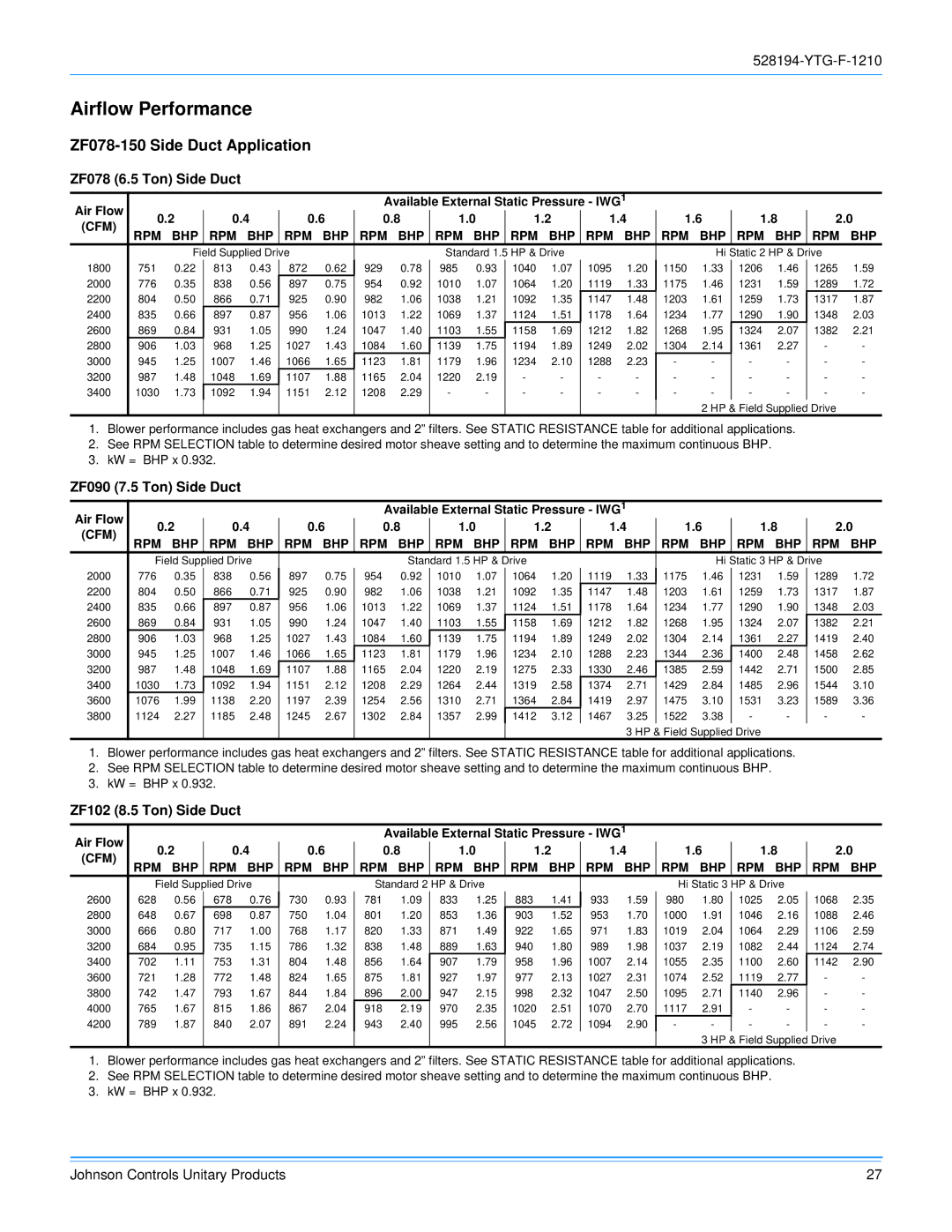
1.Blower performance includes gas heat exchangers and 2” filters. See STATIC RESISTANCE table for additional applications.

2.See RPM SELECTION table to determine desired motor sheave setting and to determine the maximum continuous BHP.

3.kW = BHP x 0.932.

ZF090 (7.5 Ton) Side Duct

Air Flow


Available External Static Pressure - IWG1


0.2

0.4

0.6

0.8

1.0

1.2


1.4

1.6


1.8


2.0


(CFM)


RPM

BHP

RPM

BHP

RPM

BHP

RPM

BHP

RPM

BHP

RPM BHP

RPM BHP

RPM BHP

RPM BHP

RPM BHP


Field Supplied Drive


Standard 1.5 HP & Drive


Hi Static 3 HP & Drive


2000

776

0.35

838

0.56

897

0.75

954

0.92

1010

1.07

1064

1.20

1119

1.33

1175

1.46

1231

1.59

1289

1.72

2200

804

0.50

866

0.71

925

0.90

982

1.06

1038

1.21

1092

1.35

1147

1.48

1203

1.61

1259

1.73

1317

1.87

2400

835

0.66

897

0.87

956

1.06

1013

1.22

1069

1.37

1124

1.51

1178

1.64

1234

1.77

1290

1.90

1348

2.03

2600

869

0.84

931

1.05

990

1.24

1047

1.40

1103

1.55

1158

1.69

1212

1.82

1268

1.95

1324

2.07

1382

2.21

2800

906

1.03

968

1.25

1027

1.43

1084

1.60

1139

1.75

1194

1.89

1249

2.02

1304

2.14

1361

2.27

1419

2.40

3000

945

1.25

1007

1.46

1066

1.65

1123

1.81

1179

1.96

1234

2.10

1288

2.23

1344

2.36

1400

2.48

1458

2.62

3200

987

1.48

1048

1.69

1107

1.88

1165

2.04

1220

2.19

1275

2.33

1330

2.46

1385

2.59

1442

2.71

1500

2.85

3400

1030

1.73

1092

1.94

1151

2.12

1208

2.29

1264

2.44

1319

2.58

1374

2.71

1429

2.84

1485

2.96

1544

3.10

3600

1076

1.99

1138

2.20

1197

2.39

1254

2.56

1310

2.71

1364

2.84

1419

2.97

1475

3.10

1531

3.23

1589

3.36

3800

1124

2.27

1185

2.48

1245

2.67

1302

2.84

1357

2.99

1412

3.12

1467

3.25

1522

3.38

-

-

-

-


3 HP & Field Supplied Drive


1.Blower performance includes gas heat exchangers and 2” filters. See STATIC RESISTANCE table for additional applications.

2.See RPM SELECTION table to determine desired motor sheave setting and to determine the maximum continuous BHP.

3.kW = BHP x 0.932.

ZF102 (8.5 Ton) Side Duct

Available External Static Pressure - IWG1

Air Flow 0.2 0.4 0.6 0.8 1.0 1.2 1.4 1.6 1.8 2.0 (CFM)

RPM BHP RPM BHP RPM BHP RPM BHP RPM BHP RPM BHP RPM BHP RPM BHP RPM BHP RPM BHP


Field Supplied Drive


Standard 2 HP & Drive


Hi Static 3 HP & Drive


2600

628

0.56

678

0.76

730

0.93

781

1.09

833

1.25

883

1.41

933

1.59

980

1.80

1025

2.05

1068

2.35

2800

648

0.67

698

0.87

750

1.04

801

1.20

853

1.36

903

1.52

953

1.70

1000

1.91

1046

2.16

1088

2.46

3000

666

0.80

717

1.00

768

1.17

820

1.33

871

1.49

922

1.65

971

1.83

1019

2.04

1064

2.29

1106

2.59

3200

684

0.95

735

1.15

786

1.32

838

1.48

889

1.63

940

1.80

989

1.98

1037

2.19

1082

2.44

1124

2.74

3400

702

1.11

753

1.31

804

1.48

856

1.64

907

1.79

958

1.96

1007

2.14

1055

2.35

1100

2.60

1142

2.90

3600

721

1.28

772

1.48

824

1.65

875

1.81

927

1.97

977

2.13

1027

2.31

1074

2.52

1119

2.77

-

-

3800

742

1.47

793

1.67

844

1.84

896

2.00

947

2.15

998

2.32

1047

2.50

1095

2.71

1140

2.96

-

-

4000

765

1.67

815

1.86

867

2.04

918

2.19

970

2.35

1020

2.51

1070

2.70

1117

2.91

-

-

-

-

4200

789

1.87

840

2.07

891

2.24

943

2.40

995

2.56

1045

2.72

1094

2.90

-

-

-

-

-

-


3 HP & Field Supplied Drive


1.Blower performance includes gas heat exchangers and 2” filters. See STATIC RESISTANCE table for additional applications.

2.See RPM SELECTION table to determine desired motor sheave setting and to determine the maximum continuous BHP.

3.kW = BHP x 0.932.

Johnson Controls Unitary Products

27

Page 27
Image 27
York R-410A manual Airflow Performance, ZF078-150 Side Duct Application, ZF078 6.5 Ton Side Duct, ZF090 7.5 Ton Side Duct

R-410A specifications

York R-410A is a widely recognized and highly efficient refrigerant used in modern air conditioning systems. Developed as an environmentally friendly alternative to R-22, R-410A has gained popularity in the HVAC industry due to its numerous advantageous features and characteristics.

One of the main features of York R-410A is its ability to provide superior cooling performance. This refrigerant operates efficiently at both high and low temperatures, allowing systems using it to maintain optimal indoor climates even during extreme weather conditions. Its high energy efficiency ratio (EER) and seasonal energy efficiency ratio (SEER) ratings make it a preferred choice for energy-conscious consumers, resulting in lower energy bills and a reduced carbon footprint.

Technologically, York R-410A systems feature advanced compressor designs that enhance their overall reliability and performance. These compressors are often equipped with variable-speed technology, enabling them to adjust their output to match the cooling demands of the space. This not only improves comfort levels but also leads to efficient energy consumption, reducing wear and tear on the equipment over time.

Another significant characteristic of York R-410A is its non-ozone-depleting properties. Unlike its predecessor R-22, which is being phased out due to its damaging effects on the ozone layer, R-410A is designed to minimize environmental impact. Its lower global warming potential (GWP) further underscores its role in promoting sustainability within the HVAC sector.

Furthermore, York R-410A systems are engineered with enhanced safety features. The refrigerant is non-toxic and non-flammable, which makes it safer for use in both residential and commercial applications. Additionally, its high thermal stability reduces the risk of breakdown or leakage, contributing to longer system lifespans and lower maintenance costs.

In conclusion, York R-410A stands out as a cutting-edge refrigerant that combines efficiency, safety, and environmental responsibility. With its advanced technologies and remarkable characteristics, it meets the demands of modern air conditioning requirements while paving the way for a sustainable future in HVAC systems. Adopting York R-410A not only benefits individual users through improved comfort and lower energy bills but also plays a vital role in protecting our planet's ozone layer and mitigating climate change.