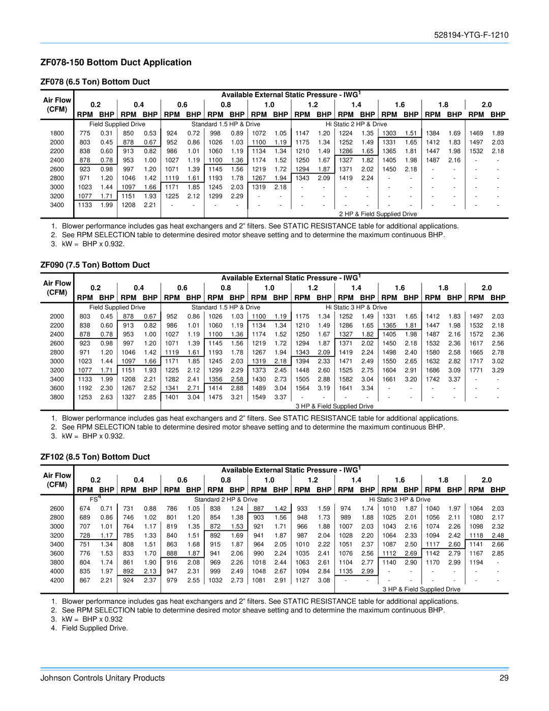
York R-410A manual ZF078-150Bottom Duct Application, ZF078 6.5 Ton Bottom Duct

Models: R-410A

1 68
Download 68 pages 3.65 Kb
Page 29
Image 29
ZF078-150 Bottom Duct Application

528194-YTG-F-1210

ZF078-150 Bottom Duct Application

ZF078 (6.5 Ton) Bottom Duct

Air Flow


Available External Static Pressure - IWG1


0.2

0.4

0.6


0.8

1.0


1.2


1.4


1.6


1.8


2.0


(CFM)


RPM

BHP

RPM

BHP

RPM BHP

RPM

BHP

RPM BHP

RPM BHP

RPM BHP

RPM BHP

RPM BHP RPM BHP


Field Supplied Drive


Standard 1.5 HP & Drive


Hi Static 2 HP & Drive


1800

775

0.31

850

0.53

924

0.72

998

0.89

1072

1.05

1147

1.20

1224

1.35

1303

1.51

1384

1.69

1469

1.89

2000

803

0.45

878

0.67

952

0.86

1026

1.03

1100

1.19

1175

1.34

1252

1.49

1331

1.65

1412

1.83

1497

2.03

2200

838

0.60

913

0.82

986

1.01

1060

1.19

1134

1.34

1210

1.49

1286

1.65

1365

1.81

1447

1.98

1532

2.18

2400

878

0.78

953

1.00

1027

1.19

1100

1.36

1174

1.52

1250

1.67

1327

1.82

1405

1.98

1487

2.16

-

-

2600

923

0.98

997

1.20

1071

1.39

1145

1.56

1219

1.72

1294

1.87

1371

2.02

1450

2.18

-

-

-

-

2800

971

1.20

1046

1.42

1119

1.61

1193

1.78

1267

1.94

1343

2.09

1419

2.24

-

-

-

-

-

-

3000

1023

1.44

1097

1.66

1171

1.85

1245

2.03

1319

2.18

-

-

-

-

-

-

-

-

-

-

3200

1077

1.71

1151

1.93

1225

2.12

1299

2.29

-

-

-

-

-

-

-

-

-

-

-

-

3400

1133

1.99

1208

2.21

-

-

-

-

-

-

-

-

-

-

-

-

-

-

-

-


2 HP & Field Supplied Drive


1.Blower performance includes gas heat exchangers and 2” filters. See STATIC RESISTANCE table for additional applications.

2.See RPM SELECTION table to determine desired motor sheave setting and to determine the maximum continuous BHP.

3.kW = BHP x 0.932.

ZF090 (7.5 Ton) Bottom Duct

Air Flow


Available External Static Pressure - IWG1


0.2

0.4

0.6


0.8

1.0


1.2


1.4


1.6


1.8


2.0


(CFM)


RPM

BHP

RPM

BHP

RPM BHP

RPM

BHP

RPM BHP

RPM BHP

RPM BHP

RPM BHP

RPM BHP

RPM BHP


Field Supplied Drive


Standard 1.5 HP & Drive


Hi Static 3 HP & Drive


2000

803

0.45

878

0.67

952

0.86

1026

1.03

1100

1.19

1175

1.34

1252

1.49

1331

1.65

1412

1.83

1497

2.03

2200

838

0.60

913

0.82

986

1.01

1060

1.19

1134

1.34

1210

1.49

1286

1.65

1365

1.81

1447

1.98

1532

2.18

2400

878

0.78

953

1.00

1027

1.19

1100

1.36

1174

1.52

1250

1.67

1327

1.82

1405

1.98

1487

2.16

1572

2.36

2600

923

0.98

997

1.20

1071

1.39

1145

1.56

1219

1.72

1294

1.87

1371

2.02

1450

2.18

1532

2.36

1617

2.56

2800

971

1.20

1046

1.42

1119

1.61

1193

1.78

1267

1.94

1343

2.09

1419

2.24

1498

2.40

1580

2.58

1665

2.78

3000

1023

1.44

1097

1.66

1171

1.85

1245

2.03

1319

2.18

1394

2.33

1471

2.49

1550

2.65

1632

2.82

1717

3.02

3200

1077

1.71

1151

1.93

1225

2.12

1299

2.29

1373

2.45

1448

2.60

1525

2.75

1604

2.91

1686

3.09

1771

3.29

3400

1133

1.99

1208

2.21

1282

2.41

1356

2.58

1430

2.73

1505

2.88

1582

3.04

1661

3.20

1742

3.37

-

-

3600

1192

2.30

1267

2.52

1341

2.71

1414

2.88

1489

3.04

1564

3.19

1641

3.34

-

-

-

-

-

-

3800

1253

2.63

1327

2.85

1401

3.04

1475

3.21

1549

3.37

-

-

-

-

-

-

-

-

-

-


3 HP & Field Supplied Drive


1.Blower performance includes gas heat exchangers and 2” filters. See STATIC RESISTANCE table for additional applications.

2.See RPM SELECTION table to determine desired motor sheave setting and to determine the maximum continuous BHP.

3.kW = BHP x 0.932.

ZF102 (8.5 Ton) Bottom Duct

Air Flow


Available External Static Pressure - IWG1


0.2

0.4

0.6


0.8

1.0

1.2

1.4


1.6


1.8


2.0


(CFM)


RPM

BHP

RPM

BHP

RPM BHP

RPM

BHP

RPM

BHP

RPM

BHP

RPM BHP

RPM BHP

RPM BHP

RPM BHP


FS4


Standard 2 HP & Drive


Hi Static 3 HP & Drive


2600

674

0.71

731

0.88

786

1.05

838

1.24

887

1.42

933

1.59

974

1.74

1010

1.87

1040

1.97

1064

2.03

2800

689

0.86

746

1.02

801

1.20

854

1.38

903

1.56

948

1.73

989

1.88

1025

2.01

1056

2.11

1080

2.17

3000

707

1.01

764

1.17

819

1.35

872

1.53

921

1.71

966

1.88

1007

2.03

1043

2.16

1074

2.26

1098

2.32

3200

728

1.17

785

1.33

840

1.51

892

1.69

941

1.87

987

2.04

1028

2.20

1064

2.33

1094

2.42

1118

2.48

3400

751

1.34

808

1.51

863

1.68

915

1.87

964

2.05

1010

2.22

1051

2.37

1087

2.50

1117

2.60

1141

2.66

3600

776

1.53

833

1.70

888

1.87

941

2.06

990

2.24

1035

2.41

1076

2.56

1112

2.69

1142

2.79

1167

2.85

3800

804

1.74

861

1.90

916

2.08

969

2.26

1018

2.44

1063

2.61

1104

2.77

1140

2.90

1170

2.99

1194

-

4000

835

1.97

892

2.13

947

2.31

999

2.49

1048

2.67

1094

2.84

1135

2.99

-

-

-

-

-

-

4200

867

2.21

924

2.37

979

2.55

1032

2.73

1081

2.91

1127

3.08

-

-

-

-

-

-

-

-


3 HP & Field Supplied Drive


1.Blower performance includes gas heat exchangers and 2” filters. See STATIC RESISTANCE table for additional applications.

2.See RPM SELECTION table to determine desired motor sheave setting and to determine the maximum continuous BHP.

3.kW = BHP x 0.932

4.Field Supplied Drive.

Johnson Controls Unitary Products

29

Page 29
Image 29
York R-410A manual ZF078-150Bottom Duct Application, ZF078 6.5 Ton Bottom Duct, ZF090 7.5 Ton Bottom Duct