Rear Panel
Table 1: | Front Panel Label and LEDs (Sheet 2 of 2) | ||
|
|
|
|
Label |
| Color | Function |
|
|
|
|
LAN |
| Green | On: The Ethernet interface is |
|
|
| successfully connected to a device |
|
|
| through the LAN port. |
|
|
|
|
|
|
| Flashing: Data transfer at LAN |
|
|
| connection |
|
|
|
|
|
|
| Off: No LAN link |
|
|
|
|
ALARM |
| Red | On: ADSL is not connected. |
|
|
|
|
|
|
| Off: ADSL is connected. |
|
|
|
|
POWER |
| Green | On: Unit is powered on. |
|
|
|
|
|
|
| Off: Unit is powered off. |
|
|
|
|
Rear Panel
LINE
RESET
CONSOLE DEFAULT LAN 1 LAN 2 LAN 3 LAN 4
Power
POWERSwitch
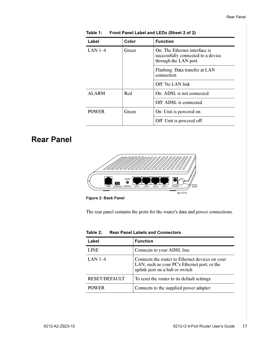
Figure 2: Back Panel
The rear panel contains the ports for the router's data and power connections.
Table 2: Rear Panel Labels and Connectors
Label | Function |
|
|
LINE | Connects to your ADSL line |
|
|
LAN | Connects the router to Ethernet devices on your |
| LAN, such as your PC's Ethernet port, or the |
| uplink port on a hub or switch |
|
|
RESET/DEFAULT | To reset the router to its default settings |
|
|
POWER | Connects to the supplied power adapter |
|
|
| 15 |
