Spalding 211014 manual 03/05

Page 24

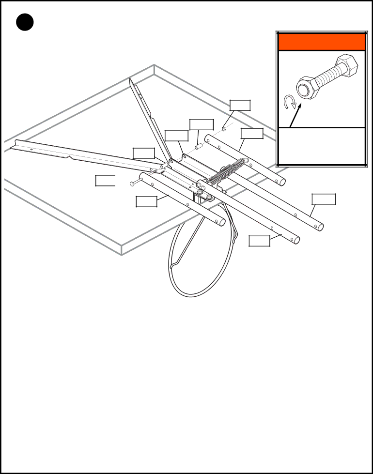
8. Assemble upper elevator tubes (P-20) to brackets using bolt (H-18), plastic spacers (H-20), and nut

(H-15) as shown.

H-20

P-21

H-20

H-18

P-20

H-15

P-20

WARNING!

TIGHTEN BOLT (H-18) IN LOCK NUT (H-15) UNTIL FLUSH (EVEN) WITH LOCK NUT’S OUTER EDGE.

P-19

P-19

P/N 211014

03/05

24

Image 24
Contents Universal Elevator Mount Before YOU Start Safety Instructions Front View Parts Identifier Item P-27 Hardware List see Hardware Identifier Hardware Identifier Bolts & Screws Hardware Identifier Plastic Spacers & Caps 13 cm Pole Sections Section B Assemble the Base 03/05 Should be facing Orientation of Struts Do not Over Flange nuts H-11 Carefully reposition Section C Assemble the Elevator System & Backboard Completed Assembly Face of Backboard Position springs P-12 against elevator tubes as shown Install Slam Jam Rim to Backboard 03/05 03/05 TOP View Clip ARM Install net P-33 Insert net into bottom of clip as shown Section D Install Front Cover & Handle Height Adjustment