Graco A-25 Transformer Primary Check, Transformer Secondary Check Replace Transformer

Page 33

Transformer Primary Check

1. Turn main power OFF

.

2.Locate the two smaller (10 AWG) wires coming out of transformer. Trace these wires back to contactor and circuit breaker (911). Use an ohmmeter to test for continuity between two wires; there should be continuity.

Repair

3.To verify transformer voltage, turn on hose zone. Measure voltage from 178CB-2 to HPOD-1; see Reactor A-25 Wiring Schematic, page 51.

Model

Secondary Voltage


310 ft.

90 Vac*


210 ft.

62 Vac*


* For 230 Vac line voltage.

Transformer Secondary Check

Replace Transformer

1. Turn main power OFF

.


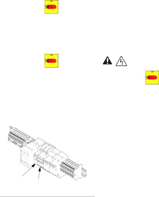
2.Locate the two larger (6 AWG) wires coming out of transformer. Trace these wires back to large green connector under hose control module and circuit breaker (909). Use an ohmmeter to test for continu- ity between two wires; there should be continuity.

If you are not sure which wire in green plug under hose module connects to transformer, test both wires. One wire should have continuity with the other transformer wire in breaker (909) and the other wire should not.

909

911

ti17999a

FIG. 11: Circuit Breaker Module

1. Turn main power OFF

. Disconnect power

supply.

2.Open Reactor cabinet.

3.Remove bolts holding transformer to cabinet floor. Slide transformer forward.

4.Disconnect the transformer wires; see Reactor A-25 Wiring Schematic, page 51.

5.Remove transformer from cabinet.

6.Install new transformer in reverse order.

3A1570A

33

Image 33
Contents Repair-Parts Important Safety InstructionsContents Systems Proportioner ModelsRelated Manuals Manual DescriptionElectric Shock Hazard Fire and Explosion Hazard Equipment Misuse Hazard Important Two-Component Material Information Changing Materials DataTrak Diagnostic Codes Temperature Control Diagnostic CodesSymbol Code Code Name Diagnosis Cause Causes of E01 Errors E01 High fluid temperatureSensor Connector Continuity Checks Pins Description Reading ChecksE03 No zone current E02 High zone currentE05 Control board over temperature E06 Communication cable unpluggedE99 Loss of communication Before Beginning Repair Pressure Relief ProcedureShutdownOpen Close ParkFlushingProblems TroubleshootingPower Pumps and PressuresProblem Cause Solution Electronics Problem Cause SolutionProblem Cause Solution See E04 Fluid Temperature Sen HeaterSor FTS or thermocouple discon Hose Heat System Problem Cause Solution Follow Pressure Relief Procedure, RepairDisconnect Pump Connect Pump Remove Air Motor Install Air MotorRecirculation / Over Pressure Relief Block Air Filter Element InstallationAir Inlet Filter / Water Separator Auto Drain Air Filter Element RemovalTemperature Control Module Connections Temperature Control ModuleConnector Description Bottom of Power ModulesTest SCR Circuit Replacing Temperature Control Assembly ModulesPrimary Heater Heater ElementLine Voltage KW Dual Zone Heater Thermocouple ThermocoupleCheck Hose Connectors Overtemperature SwitchPins Result Heated HoseFluid Temperature Sensor FTS InstallationTest/Removal Transformer Primary Check Transformer Secondary Check Replace TransformerModel Secondary Voltage Size Component Replace Circuit Breaker ModulePump Lubrication System Pump Lubrication SystemTemperature Display Refer to Reactor A-25 Wiring Schematic,Fluid Inlet Strainer Screen Display Module Detail of Membrane Switches and Temperature Display BoardReplace DataTrak Battery or Fuse Replace BatteryReplace Fuse Recommended Spare Parts Accessories7984 100 888 PartsTorque pump locking nuts to 66-74 ft-lbs 90-100 Nm Cart Part Description QtyNipple Screw Control PanelTemperature Control Wheel KitRef. Part Description Qty Fluid Inlet Kit Fluid ManifoldRing Kw Dual Zone Heater, 24J788PLUG, Pipe Air Motor Pump AssemblyAir Tubing Connections Length Connection Outside Ft m FromColor Diameter Breaker Module Phase Reactor A-25 Wiring SchematicPOD Reactor A-25 Wiring Schematic Simplified Schematic, Heater Controls Category Data Technical DataGraco Information Graco Standard Warranty
Related manuals
Manual 38 pages 32.05 Kb