Kramer Electronics Revision 6 manual Write the serial command1, as illustrated in Figure

Page 69

The Driver Manager

Write the serial command1, as illustrated in Figure 132.

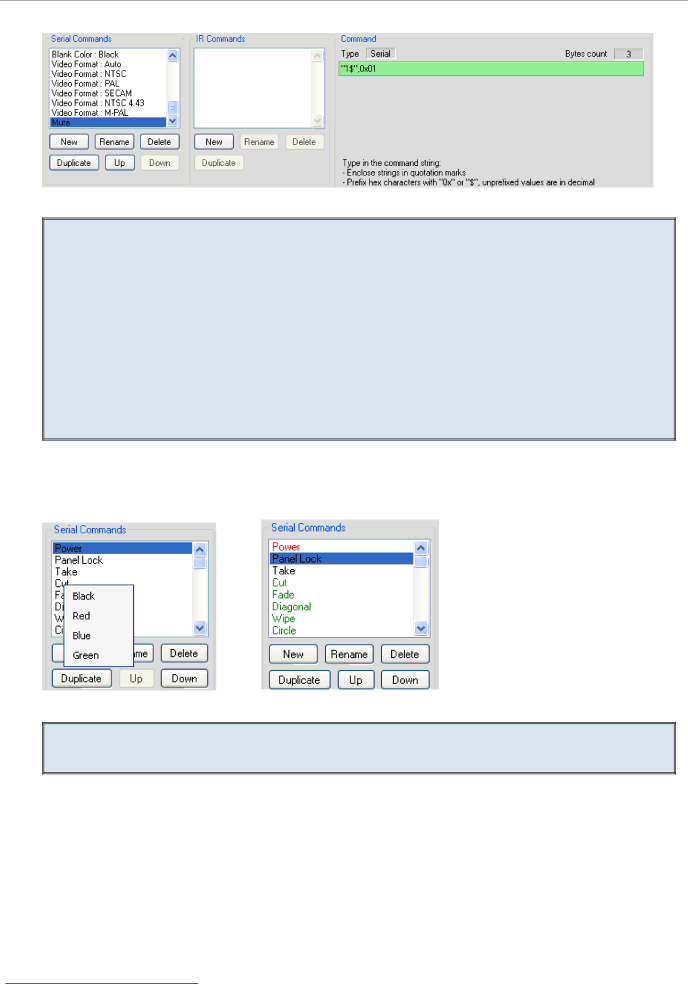
Figure 132: Writing a Serial Command

When writing a serial command:

-Enclose the strings in quotation marks (for example, "MUTE OFF")

-Prefix the hex characters with 0x or "$" (for example, 0x0D), unprefixed values are in decimal (for example, 13)

-String and byte values should be separated by commas or spaces (for example, "BRIGHT DEC",0x0D)

-If a protocol command states Carriage Return (<CR>) and/or Line Feed (<LF>) following the command line, add 0x0D or 0x0A, respectively, outside the command quotation marks,

separated by a comma.

For example, “PWR” <CR> <LF> should appear as “PWR”,0x0D,0x0A

You can color the serial commands by right-clicking them (red, blue, green or the default black), making it convenient to group them and to distinguish between outgoing and incoming commands (see Figure 133).

Figure 133: Coloring the Serial Commands

By default, protocol commands for Kramer machines are colored black for outgoing commands, red for feedback and green for queries

1 Note that if the serial command appears with a pink background, the command format is incorrect

62

KRAMER: SIMPLE CREATIVE TECHNOLOGY

Image 69
Contents Kramer K-Config Guide Revision Contents Figures Setting the LCD and Button Label Names Move the Stop Timer Action Set the New Command Table Name Tables Introduction Applicable Room ControllersApplicable Room Controllers Room Controller Commands Available Available Commands for Room Control PortsAvailable Triggers for Room Controllers Trigger Types AvailableHow to Save a Project Actions, Labels and Button Number LimitsRoom Controller Devices Limitation Quick Start To configure your Room Controller, follow these basic stepsInitial Planning GlossaryGlossary Installing the .NET Framework Revision 2.0 Software Kramer K-Config Software InstallationInstalling the USB Driver Defining the SystemInstalling Kramer K-Config Software Click OK Following window appears see FigureSelect or create a new working directory3 see Figure Downloading the Drivers Peripheral Device DriversImporting xml Templates Importing the DriversImporting the Driver Files Driver Manager Window Prior to Installing the DriversLoading the Drivers Defining the Control RoomAdding the Master Device Auxiliary Device View Device Operations Special Auxiliary DevicesBasic Virtual Device Front Panel Virtual Device appears in the Front Panel area see Figure Custom Virtual Device Appearance in K-ConfigDVD Control Virtual Device Front Panel Right click the label and buttons to name them see FigureRC-4 Remote Controller Defining the Port Manager Tab Area SettingsSelecting a Driver Drivers Tree WindowWriting a Port Description Defining the Ethernet Ports Edid file is uploaded Select the Edid file to upload and click OpenConnect Dialog Box Device Settings TabDST Device Settings Tab FeaturesSetting the Date and Time Summarizes date and time setting optionsWeb Settings Window Web Settings TabBuilt-in Triggers TriggersSelect the desired port for example, RS-232.DType Adding Actions to a TriggerSelecting the Command All On Trigger with actions assigned Replacing an ActionSelecting a New Action Selecting the Action to be replaced from the Action ListType the name of the custom trigger, and then click OK Adding a Custom TriggerScheduling Window Set the ScheduleAdd actions to the trigger see Section Monitor Event TriggerTimer Trigger Flowchart Power on Example Add Timer TriggerSet the Timeout Timer Trigger in the Triggers ListSelecting the Timer Start/Stop Action Projector Power on Command in the Button Trigger Action ListStep III Define the Monitor Event System Inactivity Example Add the following actions2 see Section Set the timeout to 20 minutes1Add the Start Timer trigger Add the Stop Timer triggerAdd GPI/O Trigger Button GPI/O TriggerDigital Input Add actions to the new trigger see Figure Select the condition for activating the triggerGPI/O Defined as Digital Output Select the trigger behaviorSelect the Behavior of the Digital Input Trigger Button TriggerSelect the Button Behavior Button Trigger Properties WindowToggle Number in the Action List Button Trigger Properties Window ToggleAction Type Knob Turning TriggerShows the port command actions1 Button Color Selection Shows the available button ignore statesSwitcher Command Action Type Shows the unlock PIN code Definition of 4 States Select LEDs to LightStates Action Type Setting the State Action ListDelay Action Type Click Yes to write the configuration to the device Write the Configuration Click OK to connect Setting K-NET ID window appears Set K-NET IDs Click OK to set the ID number Driver Manager Driver Manager Window Driver Manager Window FeaturesNew Serial Command Window Creating a Driver CommandWriting a Serial Command Write the serial command1, as illustrated in FigureCreating an IR Command New IR Command Window Creating Serial Range Commands Click the Table Details button Click OKSetting the Number of Command Rows Writing the Commands Logarithmic Row Selection Setting a Specific Volume Level Adding Actions to a Trigger via the Command TableAdding the Commands Table to the List Add the Command table to the listSelecting commands 0 to Defining Queries Selecting commands in the Port Command AreaQuery Format Details Feature FunctionQuery Details Window Lamp Hour Query Response FormatsProjector Query Response Lamp Hours Writing the Query Command Lamp HoursLamp Hour Query Format Details Shows the query format detailsWriting the Query Command Power Power Query Response FormatsQuery Format tab, set the query format, see Figure Projector Query Response PowerExpected Result Table Power This section describes the Kramer K-Configmenus Kramer K-Config MenusFile Menu Features File MenuSaving a Project Export Device xml File Select Virtual Device to SaveDevice Menu Device Menu FeaturesConnect Window Load Firmware Upgrade Window SV-551Help Menu Help Menu FeaturesLocal Area Connection Properties Window Connecting via the Ethernet