6
AIR FOR COMBUSTION AND VENTILATION
Determining
AIR FOR COMBUSTION AND VENTILATION
Continued
The space in the example on page 5 is a confined space because the actual Btu/Hr used is more than the maximum Btu/Hr the space can support. You must provide additional fresh air. Your options are as follows:
A. Rework worksheet, adding the space of an adjoining room. If the |
extra space provides an unconfined space, remove door to adjoining |
room or add ventilation grills between rooms. See Ventilation Air From |
Ventilation
Grills
Into Adjoining
12"
Ventilation Grills Into Adjoining Room,
Inside Building. |
Room,
Or
Option 2
Option 1
Remove
B. | Vent room directly to the outdoors. See Ventilation Air From Outdoors. |
C. | Install a lower Btu/Hr heater, if lower Btu/Hr size makes room unconfined. |
If the actual Btu/Hr used is less than the maximum Btu/Hr the space can support, the space is an unconfined space. You will need no additional fresh air ventilation.
![]() WARNING: If the area in which the heater may be operated is smaller than that defined as an uncon- fined space or if the building is of unusually tight construction, provide adequate combustion and ven- tilation air by one of the methods described in the National Fuel Gas Code, ANSI Z223.1/NFPA 54 Sec- tion 5.3 or applicable local codes.
WARNING: If the area in which the heater may be operated is smaller than that defined as an uncon- fined space or if the building is of unusually tight construction, provide adequate combustion and ven- tilation air by one of the methods described in the National Fuel Gas Code, ANSI Z223.1/NFPA 54 Sec- tion 5.3 or applicable local codes.
VENTILATION AIR
Ventilation Air From Inside Building
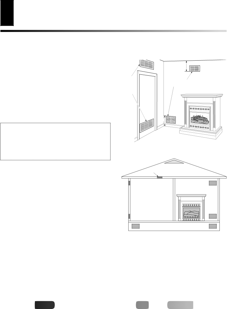
This fresh air would come from an adjoining unconfined space. When ventilating to an adjoining unconfined space, you must provide two permanent openings: one within 12" of the ceiling and one within 12" of the floor on the wall connecting the two spaces (see options 1 and 2, Figure 3). You can also remove door into adjoining room (see option 3, Figure 3). Follow the National Fuel Gas Code, ANSI Z223.1/NFPA 54, Section 5.3, Air for Combustion and Ventilation for required size of ventilation grills or ducts.
Ventilation Air From Outdoors
Provide extra fresh air by using ventilation grills or ducts. You must provide two permanent openings: one within 12" of the ceiling and one within 12" of the floor. Connect these items directly to the outdoors or spaces open to the outdoors. These spaces include attics and crawl spaces. Follow the National Fuel Gas Code, ANSI Z223.1/NFPA 54, Section 5.3, Air for Combustion and Ventilation for required size of ventilation grills or ducts.
IMPORTANT: Do not provide openings for inlet or outlet air into attic if attic has a
Door into Adjoining Room, Option ![]() 3
3
12"
Figure 3 - Ventilation Air from Inside Building
Ventilated
Outlet Attic
Air
Outlet |
|
Air | To Attic |
|
To
Crawl
Space
Inlet
Air
Inlet Air |
| Ventilated |
|
| Crawl Space |
|
|
Figure 4 - Ventilation Air from Outdoors
![]()
![]()
![]()
![]()
![]() For
For![]()
![]()
![]()
![]()
![]()
![]()
![]()
![]()
![]()
![]()
![]()
![]()
![]() .
.![]()
![]()
![]()
![]() .com
.com![]()
![]()
![]()
![]()
![]()