Furuno FS-1503 manual Operation, System Configuration

Page 6

1.OPERATION

1.1System Configuration

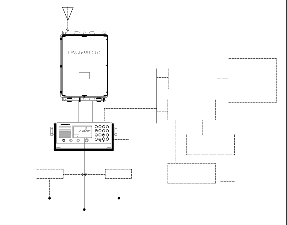
The basic FS-1503 consists of a Transceiver Unit, an Antenna Coupler, and an MIC. The figure below shows the FS-1503 system and optional equipment.

FS-1503 SYSTEM CONFIGURATION

Antenna Coupler

AT-1503

Transceiver Unit


*


FS-1503

SSB TRANSCEIVER FS-1503


MODE

CURS

CLARI


AGC

STATION


1

2

3

TX


SQL

SCAN

RX


SIMP

R


4

5

6


0

2

4

6

8

10 S


AGC NB


TUNE

H/L


CH


H3E

7

8

9


MIC


START

External

MICVOLUME


RF GAIN

FREQ/CH

2182

INT

ALM

ENT


0


OFF


TEST


(Handset


Speaker

optionally


available)


PC-220 13.6 V

13.6 V

PR-270


24 VDC


100/110/200/220 VAC


13.6 VDC


DSC Terminal

Distributor

DSC-5/6

NBDP Terminal

DB-500

DP-5/6

OR

Remote Station

RB-500


Distributor


DB-120


DSC Terminal

DSC-5/6

NBDP Terminal

DP-5/6

Option

*Optional pcb (REMOTE A or REMOTE B) required.

Figure 1-1 FS-1503 system configuration

1-1

Image 6
Contents Page Page Safety Instructions Table of Contents Features IntroductionSystem Configuration OperationTransceiver Unit Description Rotary controlsKeys Indications ALMTurning the Loudspeaker On/Off Turning the Power On/OffAdjusting the Backlighting Turning the Squelch On/OffSelecting Frequency Turning AGC on/offTx frequency Direct frequency entryRx frequency Paired Rx/Tx frequencyUser channels J3EITU telephony channels SSB Sample displays of ITU telephony channelITU Telex channels TLXTuning the antenna Displaying Station NameTransmitting Reducing transmitter power Using the microphoneMonitoring transceiver output power Distress Call on 2182 kHzDistress frequencies Distress calls and Distress messageReceiving Adjusting RF gainClarifier adjustment MeterReceiving AM broadcasting stations Squelch controlNoise blanker NB Frequency Scan Channel scanUser channels ITU channels 12 Sample scan screenFrequency Sweep MIF Commands MIF commands applicable to the FS-1503Operation of Optional Equipment Telex CommunicationFuruno Nbdp Terminal DP-5/DP-6 Priority Remote Station RB-500 requires optional Remote-B BoardIntercom Communication on 2182 kHzChanging System Settings System SetupCustomizing by User Scan/sweep-stop signal level Writing User Channels Testing the transmitter with a dummy antenna MaintenanceAural testing Weekly ChecksDiagnostic Test Sequence of diagnostic testLCD/Keyboard Test & ROM Version No. Confirmation Key and corresponding indicationMaintenance MaintenanceMaintenance con’t Troubleshooting Troubleshooting ListTroubleshooting list con’t Errow Indication Replacing FusesSpecifications GeneralAntenna Coupler Appendix Custom CHANNELS/FREQUENCIESMF band working carrier frequencies ref. US CFR 47 Part MF band SSB working carrier frequencies CH noMHz ITU SSB carrier frequencies ITU RR Appendix ITU CH noFollowing frequencies are factory programmed 12/16 MHz ITU SSB carrier frequencies ITU RR Appendix CH no Ship RX Ship TX Telex Channels MF Band Telex Frequency TableMHz Band ITU Nbdp Telex Frequency Table ITU RR Appendix8001 12001 12/16 MHz Band ITU Nbdp Telex Frequency Table 16111 18/19 MHz Band ITU Nbdp Telex Frequency Table CH NO. Ship RX Ship TX22001 22, 25/26 MHz Band ITU Nbdp Telex Frequency Table Index
Related manuals
Manual 50 pages 63.4 Kb