antenna in the Wireless Weather Station. However, due to the nature of the Earth’s Ionosphere, reception is very limited during daylight hours. The Wireless Weather Station will search for a signal every night when reception is best. The WWVB radio station derives its signal from the NIST Atomic clock in Boulder, Colorado. A team of atomic physicists continually measure every second of every day to an accuracy of ten billionths of a second a day. These physicists have created an international standard, measuring a second as 9,192,631,770 vibrations of a Cesium 133 atom in a vacuum. For more information about WWVB please see the NIST website at http://www.boulder.nist.gov/timefreq/stations/wwvb.htm
QUICK SET-UP GUIDE
Hint: Use good quality Alkaline Batteries and avoid rechargeable batteries.
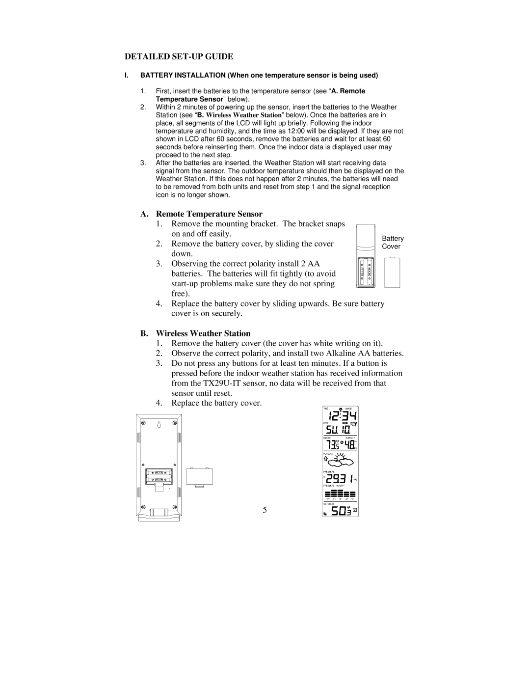
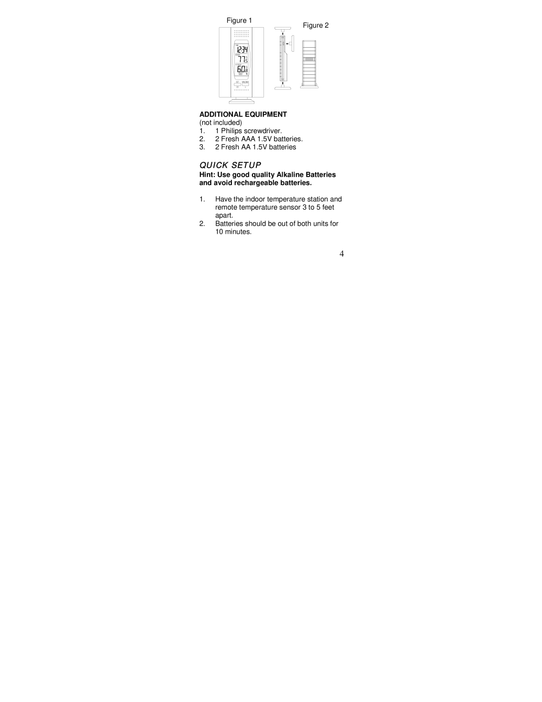
1.Have the Wireless Weather Station and remote temperature sensor 3 to 5 feet apart.
2.Batteries should be out of both units for 10 minutes.
3.Place the batteries into the remote temperature sensor first then Wireless
Weather Station.
(All remote temperature sensors must be started before the Wireless Weather
Station)
4.DO NOT PRESS ANY BUTTONS FOR 15 MINUTES.
In this time the Wireless Weather Station and remote temperature sensor will start to talk to each other and the display will show both the indoor temperature and humidity, and an outdoor temperature. If the Wireless Weather Station does not display both temperatures after the 15 minutes please retry the set up as stated above. After both indoor and outdoor temperatures are displayed for 15 minutes you can place your remote temperature sensor outdoor and set your time.
The remote temperature sensor should be placed in a dry, shaded area. The temperature sensor has a range of 330 feet. Keep in mind that the 330 feet is in open air with no obstructions and that radio waves DO NOT curve around objects. Actual transmission range will vary depending on what is in the path of the signal. Each obstruction (roof, walls, floors, ceilings, thick trees, etc.) will effectively cut signal range in half.
Example: A Wireless Weather Station with a 330 feet range is mounted on an interior wall, so that the signal has to pass through one interior wall, one exterior wall, and across the 10 feet width of the room between the 2 walls. The first wall will reduce the range to 165 feet, and the second wall will reduce the range to 87 feet. Factoring in the 10 foot room, this leaves a maximum of 77 feet of remaining signal range.
This allowance is typically enough for a frame wall with
4
