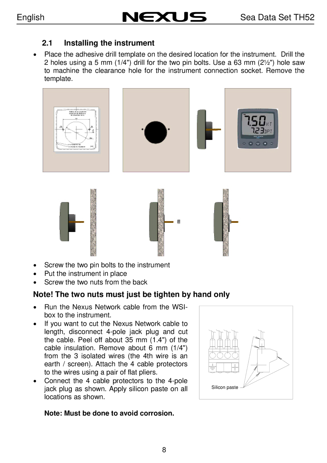
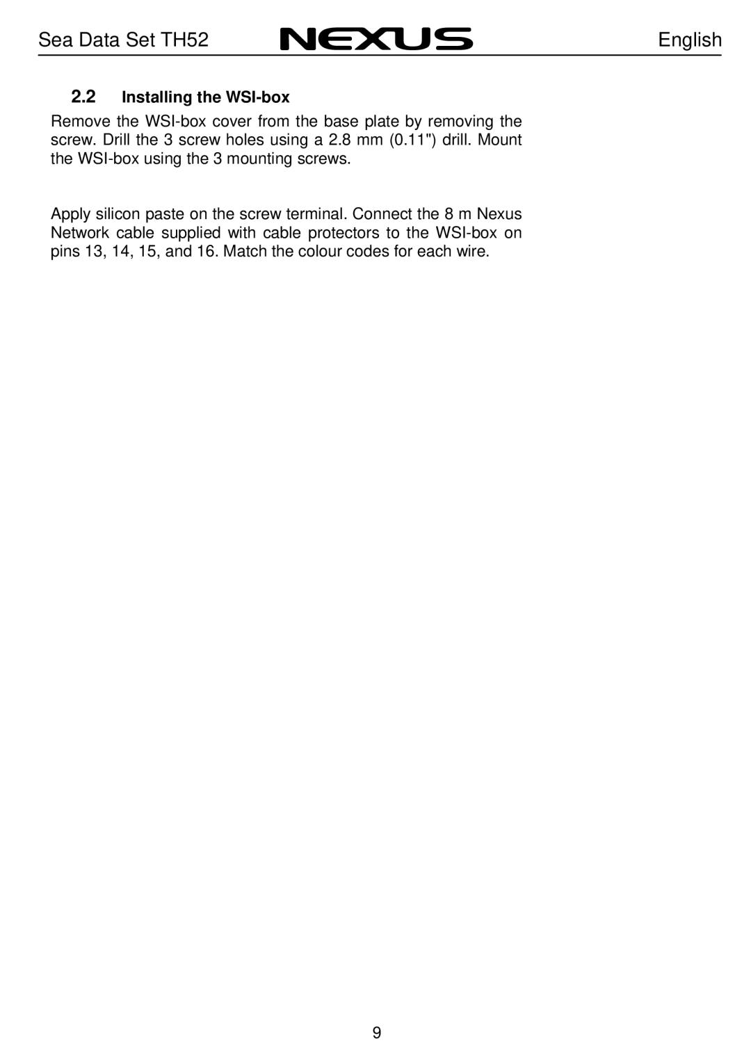
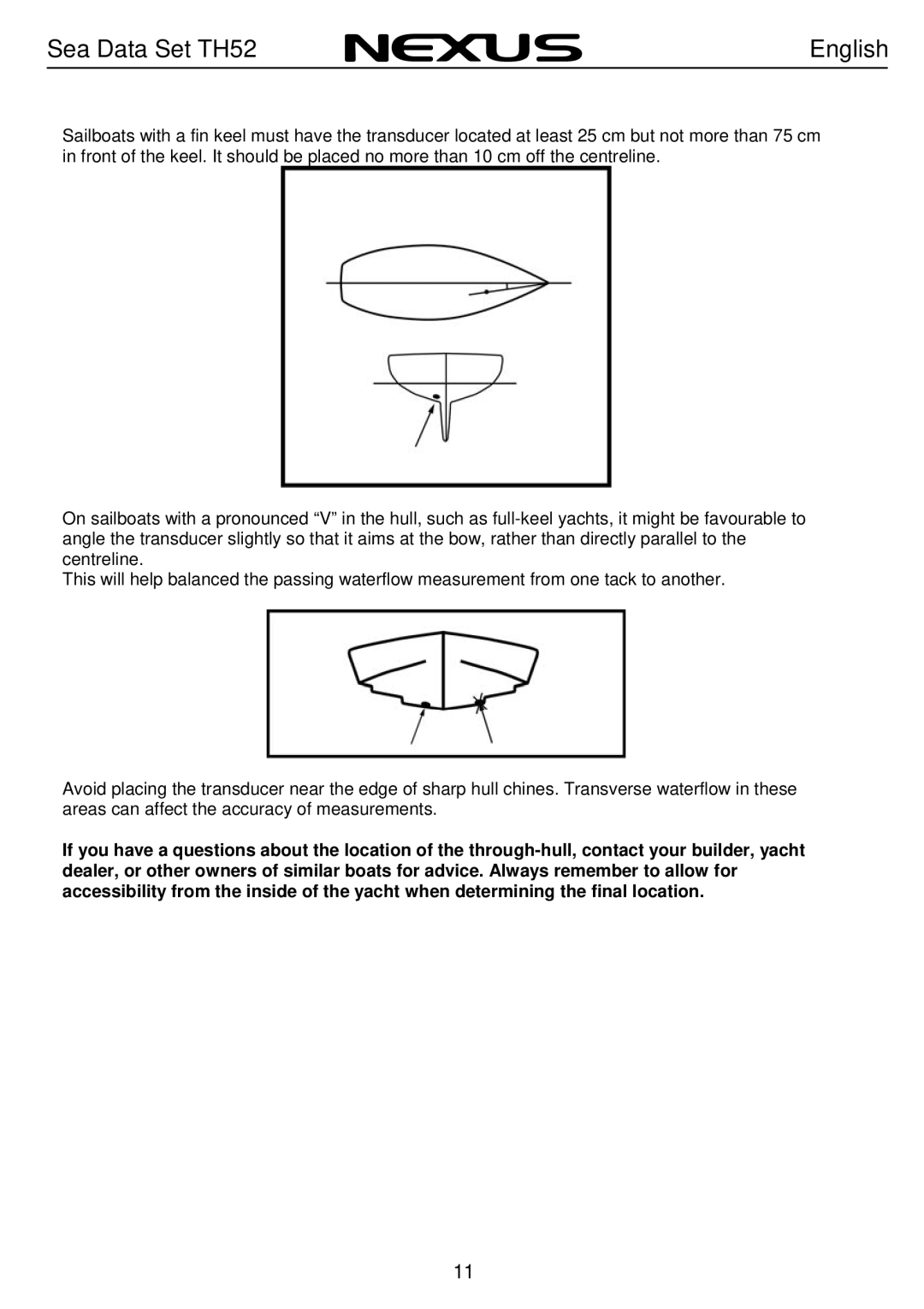
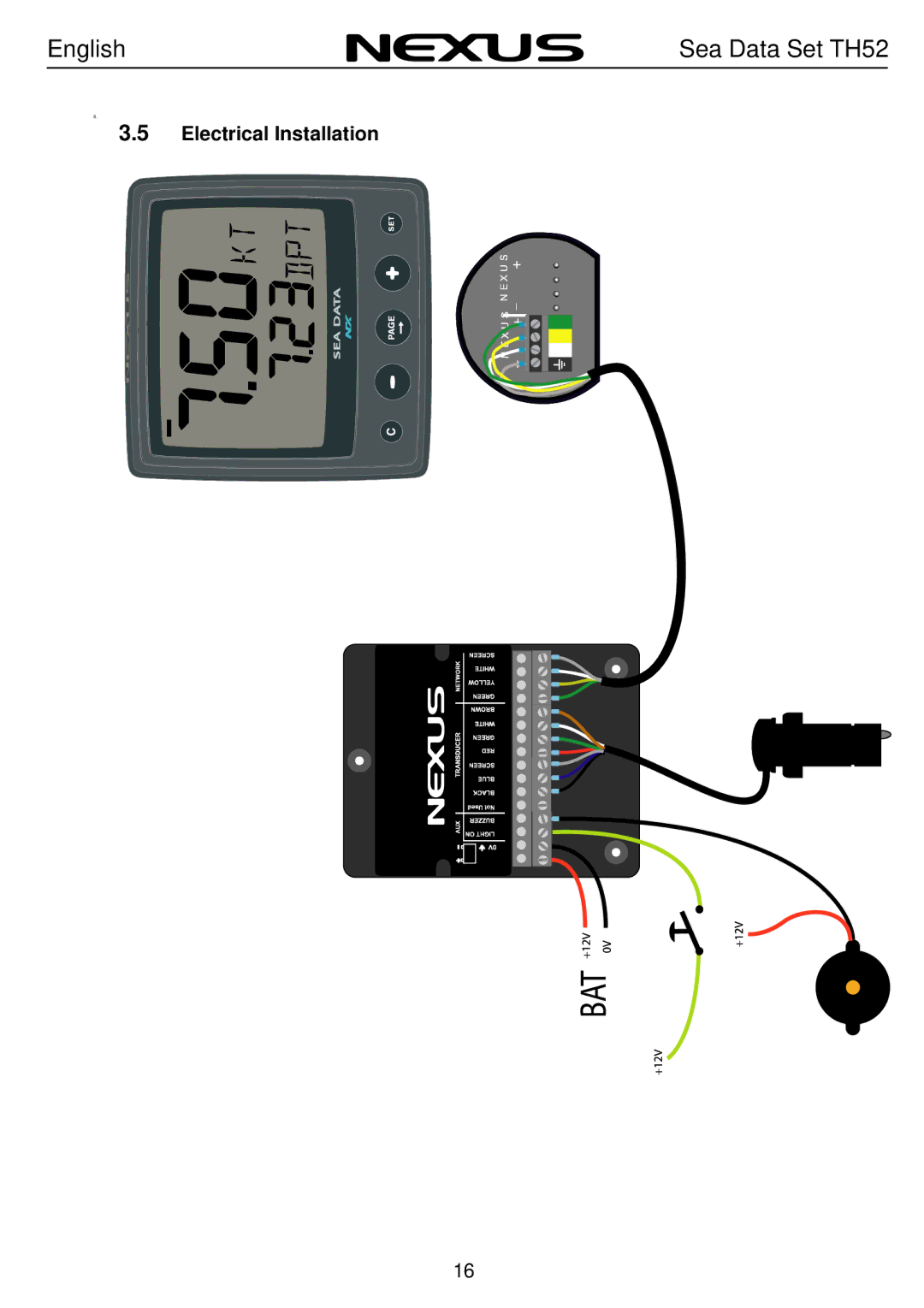
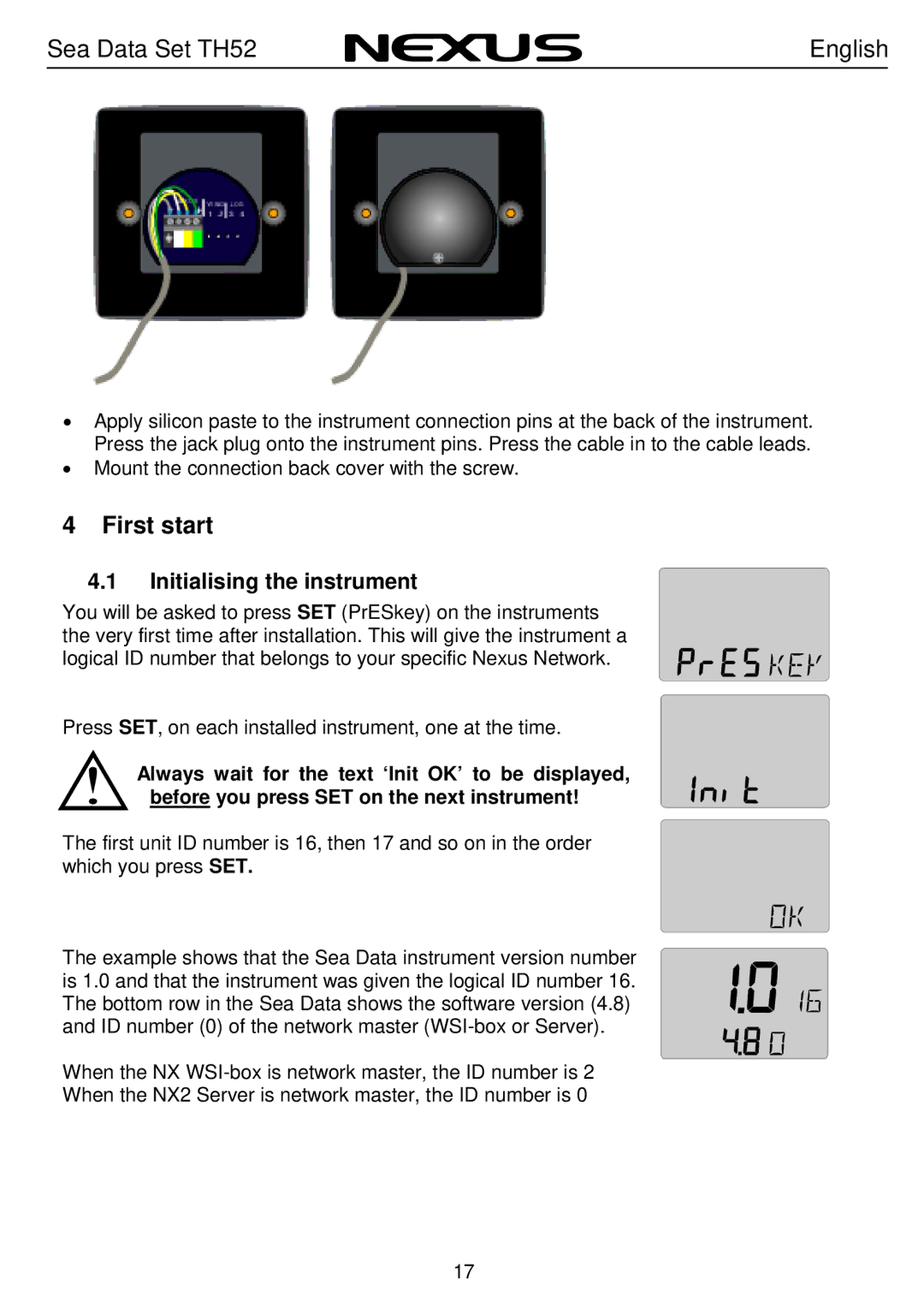
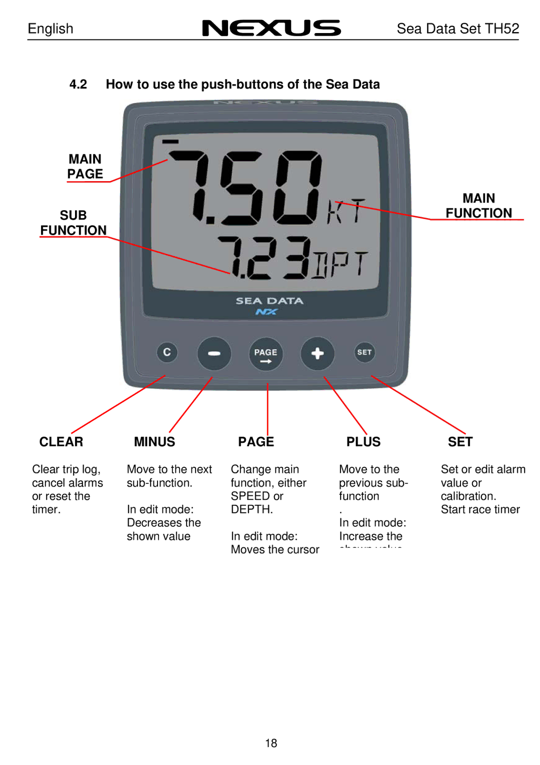
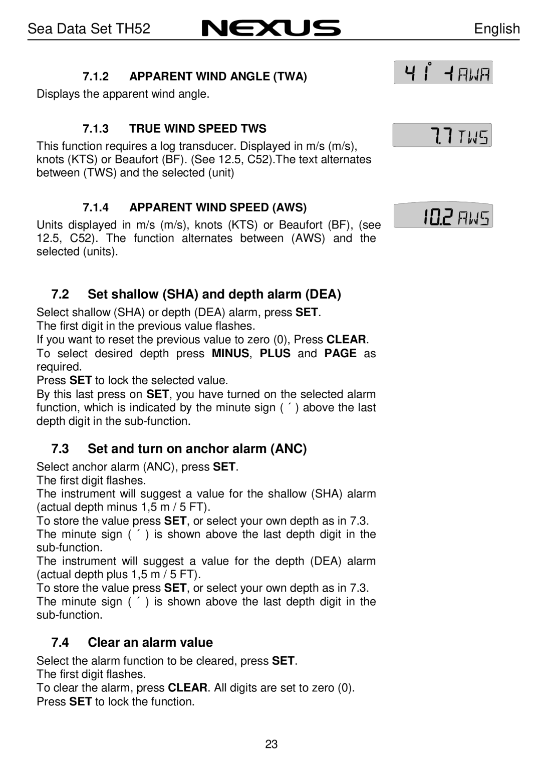
Nexus 21 TH52 operation manual Checking for Leaks, Installation in a Cored Fiberglass Hull

Page 15

English

Sea Data Set TH52

10.Attach one safety ring to one end of the retaining pin. Slide the retaining pin through the valve assembly and paddlewheel insert. Attach the second safety ring to the retaining pin (see Figure 2).

Warning: Always attach the safety wire to prevent the insert from backing out in the unlikely event that the cap nut fails or is screwed on incorrectly.

11. Attach the safety wire to one eye in the hull nut. Thread the short emergency plug onto the wire. Lead the wire in a counterclockwise direction and thread it through one eye in the cap nut. Thread the wire through the eye a second time. Then lead the wire through the pull ring and the second eye in the cap nut. Twist the wire securely to itself.

12.Route the cable to the instrument being careful not to tear the cable jacket when passing it through the bulkhead(s) and other parts of the boat. To reduce electrical interference, separate the sensor cable from other electrical wiring and the engine. Coil any excess cable and secure it in place with zip-ties to prevent damage.

13.Refer to the instrument owner’s manual to connect the sensor to the instrument.

3.3Checking for Leaks

Warning: Never install a thru-hull sensor and leave the boat in the water unchecked for several days.

When the boat is placed in the water, immediately check around the thru-hull sensor for leaks. Note that very small leaks may not be readily observed. It is best not to leave the boat in the water for more than 3 hours before checking it again. If there is a small leak, there may be considerable bilge water accumulation after 24 hour. If a leak is observed, repeat “Bedding” and “Installing” on page 2 immediately.

3.4Installation in a Cored Fiberglass Hull

The core (wood or foam) must be cut and sealed carefully. The core must be protected from water seepage, and the hull must be reinforced to prevent it from crushing under the hull nut allowing the housing to become loose. Warning: Always wear safety goggles and a dust mask.

14

Image 15
Contents NX Sea Data Set Sea Data Set TH52 English Edition April Speed functions 10.1 Registering this product Part specificationNX Sea Data Few do not you should consider InstallationInstallation includes 6 major steps Following material is needed Wire cutters and strippersInstalling the instrument Installing the WSI-box Example Sea Data Set TH52 English Hole Drilling InstallingInstalling the through hull fittings BeddingSea Data Set TH52 English Checking for Leaks Installation in a Cored Fiberglass HullSea Data Set TH52 English Electrical Installation Initialising the instrument First startMain Subfunction Function Clear Minus Plus SET How to use the push-buttons of the Sea DataInstrument backlight Function overview of the Sea DataSpeed functions Speed main-functionSpeed sub-functions Depth unit/DPT Maximum Speed MAXDepth functions Boat Speed BSP/unitBarometric pressure unit/hPA Set shallow SHA and depth alarm DEA Set and turn on anchor alarm ANCClear an alarm value Turning OFF or on an alarm Silencing an alarmMove and lock a sub-function Select power on functionCancel a moved or locked sub-function Customise your displayUnit for Speed, C11 Unit KTS Calibration setting up the Sea Data instrumentCalibration of speed C10 Return C10 RETUnit for Temp readings, C16 UnitC Adjust Depth readings, C15 00.0 ADJDamping of Speed, C13 SEA Unit for Depth readings, C14 Unit mUnit for Air Pressure, C18 Unit hPA Adjustment of Temp reading,C17 0C TMPAdjustment of Wind Angle, C20 000 ADJ Key beep setting, C22 OFF KEYGeneral fault finding Maintenance and fault findingMaintenance Fault findingWind No reading Fault action Speed and distance functions No readingSpecifications Technical specifications Sea DataTechnical specifications WSI-box Waranty Sea Data Set TH52 English English Sea Data Set TH52 Nexus Marine AB