Lincoln Electric TIG 375 Internal SET UP Controls, TIG Welding Features, Stick Welding Features

Page 23

B-8

OPERATION

B-8


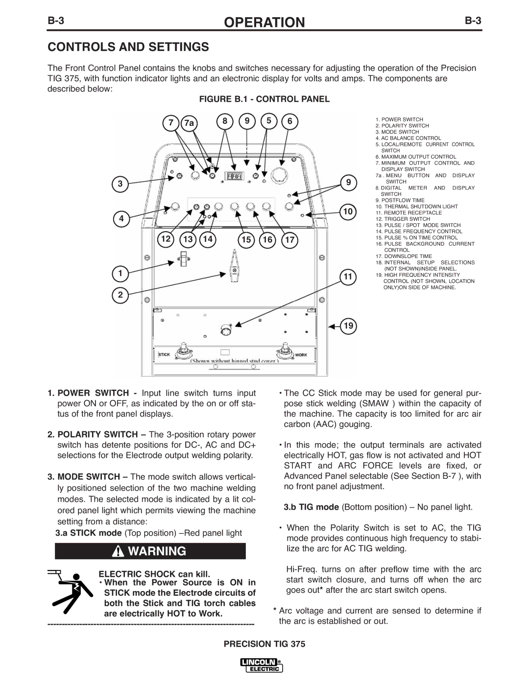
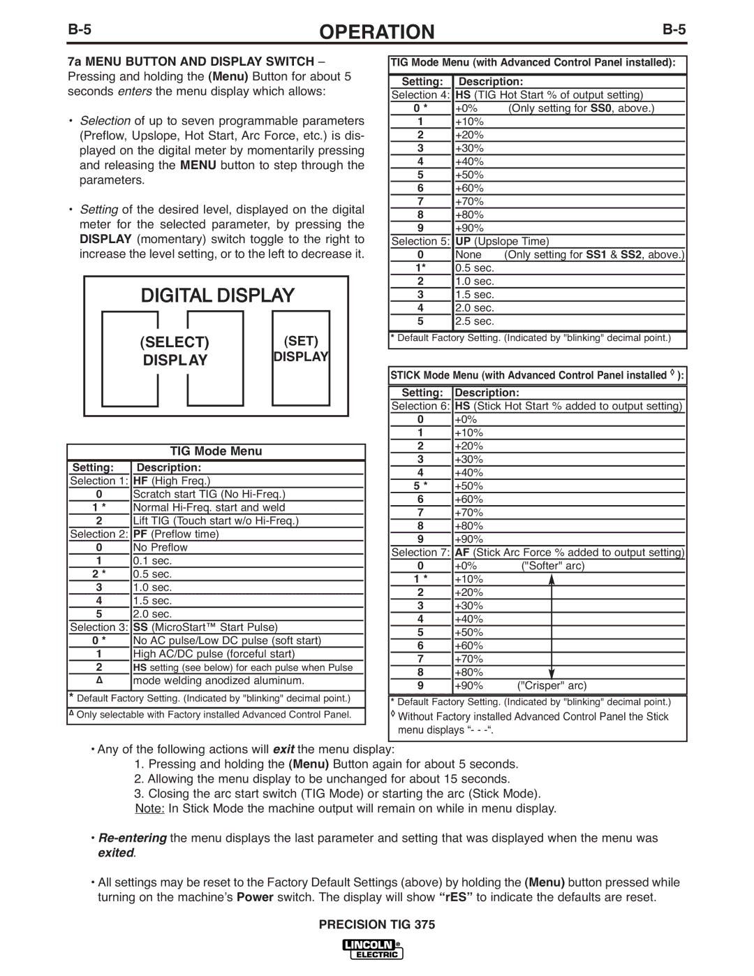
INTERNAL SET UP CONTROLS

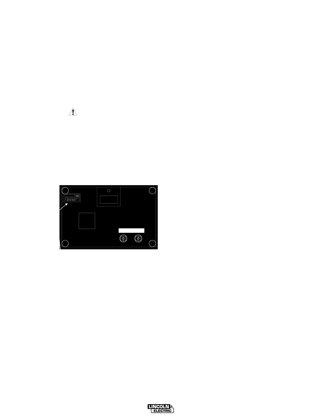
Precision TIG 375 Advanced Panel has the following additional control features which are set up using the DIP Switch (S1) provided on the internal panel of this option.

Access to this internal panel is obtained by removing the two screws securing the top corners of the Precision TIG front control panel and swinging the con- trol panel down to reveal the panel mounted on the sur- face of the Precision TIG Control board:

CAUTION

THE CONTROL BOARDS CONTAIN STATIC SEN- SITIVE COMPONENTS

To avoid possible damage to these components be sure to ground yourself by touching the

machineʼs sheet metal while handling or making settings on the internal control box components.

------------------------------------------------------------------------

PRECISION TIG ADVANCED PANEL

(M21115 Internal Panel)

TIG WELDING FEATURES

The following DIP switch feature selections function only when the Precision TIG is set to TIG mode (See Item 3):

• Switch #1 Postflow Time Extension* (See Item 9)

ON – Doubles the time ranges.

OFF – Standard time range (as shipped).

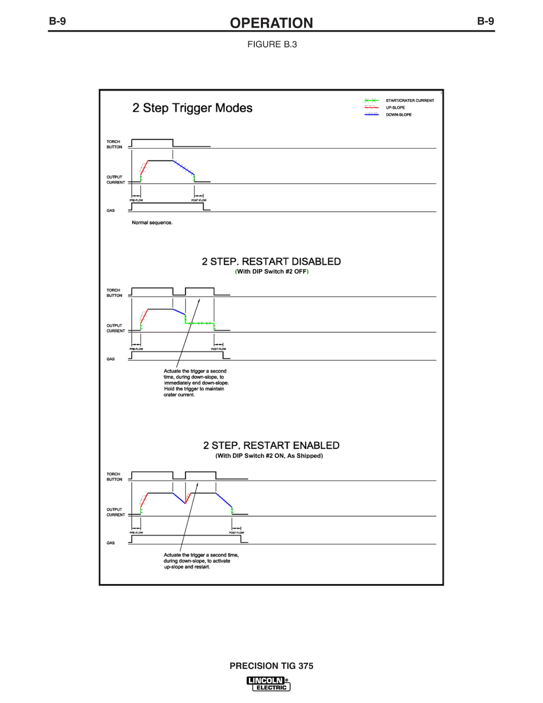
Switch #2 2-Step Trigger Restart Feature (See Figure B.3)

ON – Restart Enabled (as shipped).

OFF – Restart Disabled.

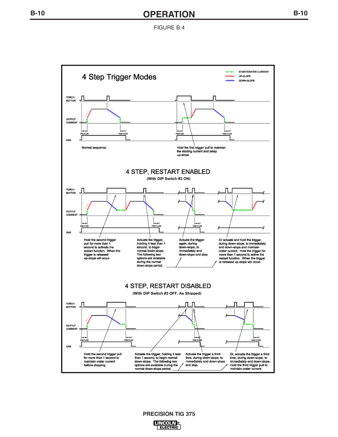
Switch #3 4-Step Trigger Restart Feature (See Figure B.4)

ON – Restart Enabled.

OFF – Restart Disabled (as shipped)

• Switch #4 Lift TIG Starting - Does not function

(See Item 7a)

• Switch #5 Crater-Fill Level (See Item 7)

DIP SWITCH (S1)

^ ON

1 2 3 4 5 6 7

ON - Level is minimum rating of the machine (2A) OFF – Level (as shipped) is Minimum Output setting

(same as Start level).

(DOES NOT FUNCTION)

HOT START

F

ARC FORCE


ON

1

2

3

4

5

6

7

8

OFF

DIP SWITCH POSITIONS (FACTORY SETTINGS)

STICK WELDING FEATURES

• Switch #6 Hot Start Level – Does not function (See Item 7a)
Switch #7 Arc Force Level – Does not function (See Item 7a)

PRECISION TIG 375

Image 23
Contents Precision TIG Safety Depends on YouCalifornia Proposition 65 Warnings SafetyElectric Shock can kill Iii Welding and Cutting Sparks can Cause fire or explosionSûreté Pour Soudage a LʼArc Précautions DE SûretéThank You Table of Contents Precision TIG InstallationRated Input Single Phase only Duty Cycle-Applications Volts at Rated Amperes AmpsAdditional Output Capacity Recommended Input Wire and Fuse SizesPhysical Dimensions Temperature RangesSafety Precautions Input and Grounding Connections Stick Electrode Cable Connection Output CABLES, Connections and LimitationsWork Cable Connection Figure A.2 TIG Torch ConnectionFigure A.3 Auxiliary Power ConnectionsFigure A.4 Robotic Interface ConnectionWelding Sparks OperationProduct Description Pipe ThawingEquipment Limitations Recommended Processes and EquipmentRecommended Processes Process LimitationsFigure B.1 Control Panel Controls and SettingsOperation Display TIG Mode MenuAdvanced Panel Controls Do not USE 4-STEP if Using AN Amptrol RemoteOperation Stick Welding Features Internal SET UP ControlsTIG Welding Features Figure B.3 Figure B.4 Setup Guidelines for TIG Welding With AN Amptrol TIG Weld Cycle ChartFigure B.6 Gtaw Process Making a TIG Weld with AN AmptrolSmaw Process Optional Equipment AccessoriesFactory Installed Options Field Installed OptionsOverload Protection MaintenanceSafety Precautions Routine and Periodic MaintenanceUNDER-COOLER Service Service ProceduresComponent Access Spark GAP AdjustmentHOW to USE Troubleshooting Guide TroubleshootingCourse of Action SymptomsOutput Problems GAS Problems Meter ProblemsHI-FREQ Problems Preset & Output Control Problems TIG Welding Problems Stick Welding ProblemsTIG Problems Wiring Diagram Wiring Diagram Dimension Print K2622-1 Domestic Precaucion Aviso DE