


Maintenance | |
|
|
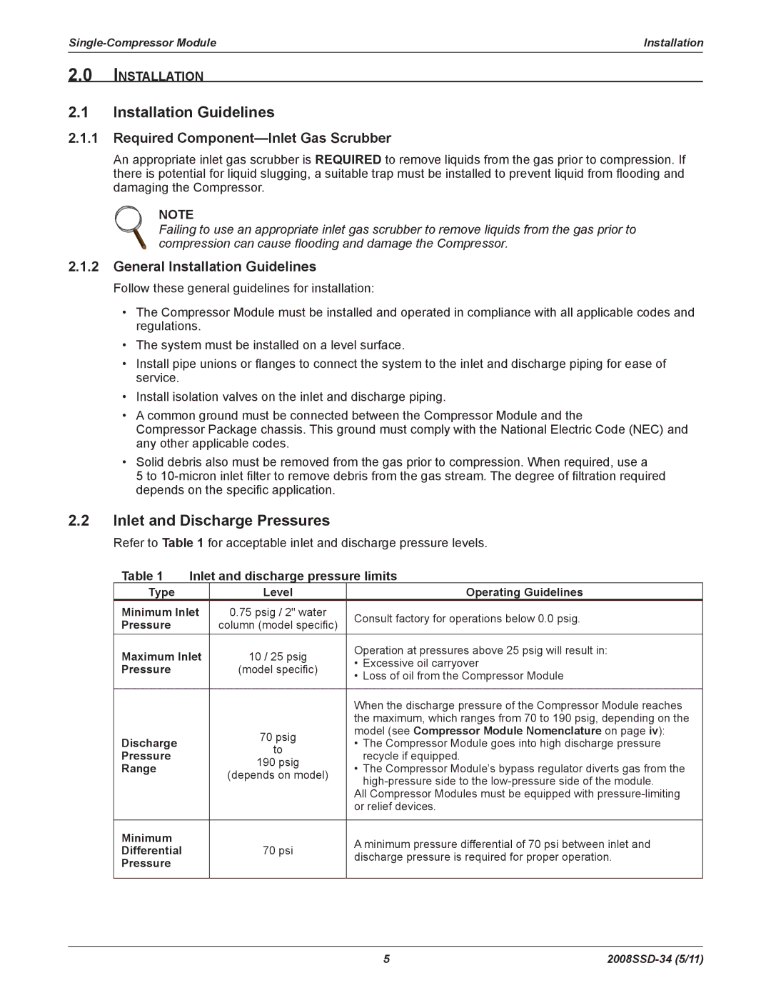
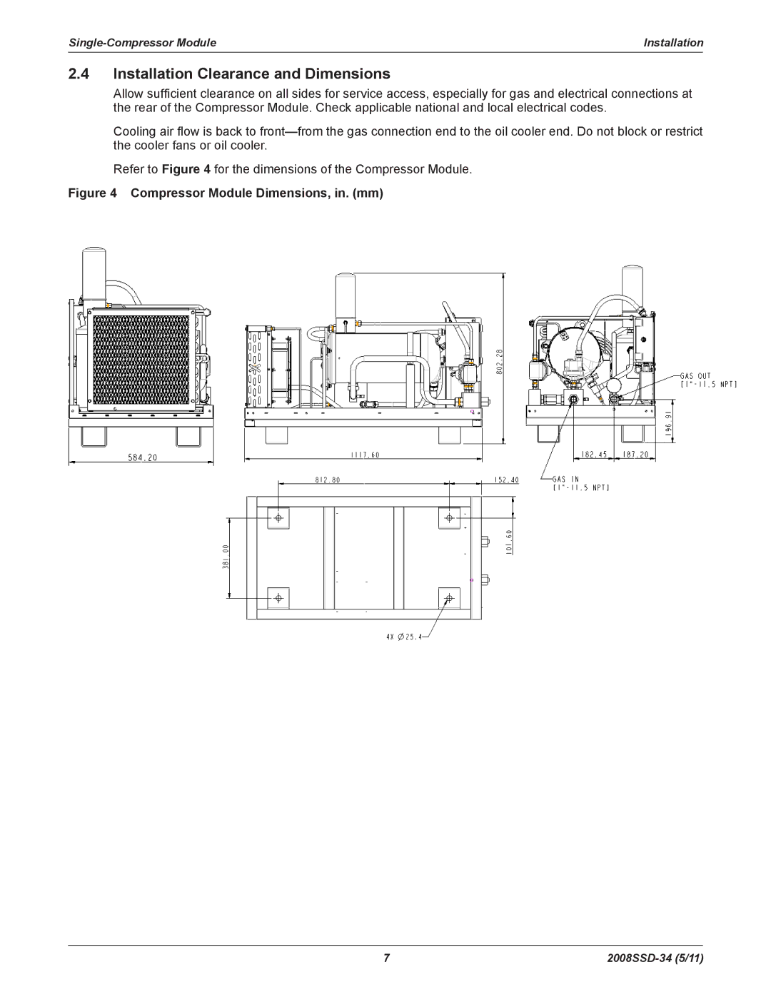
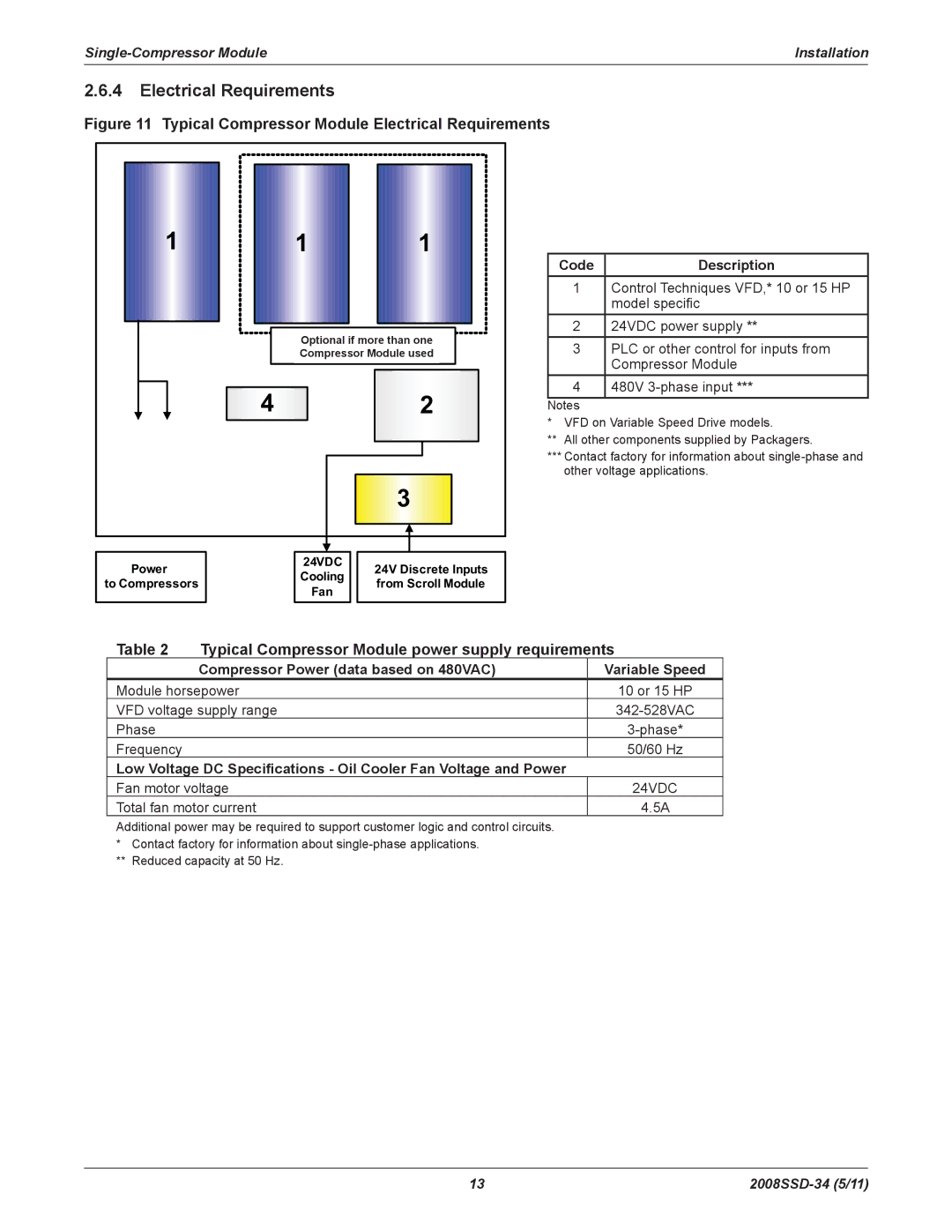
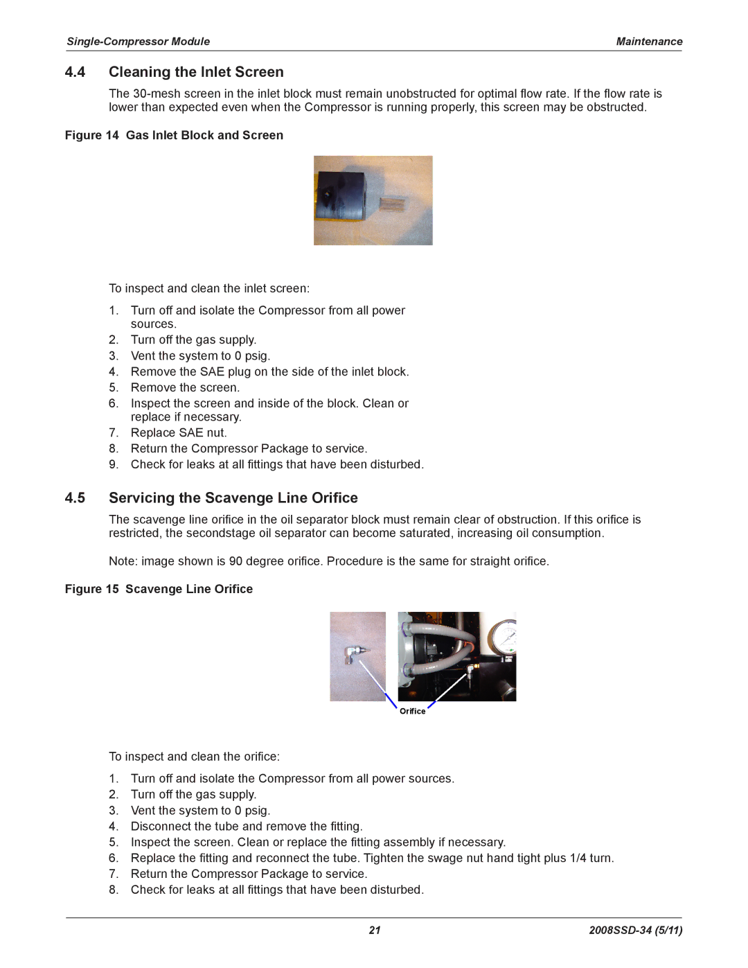
4.2Maintenance Tools
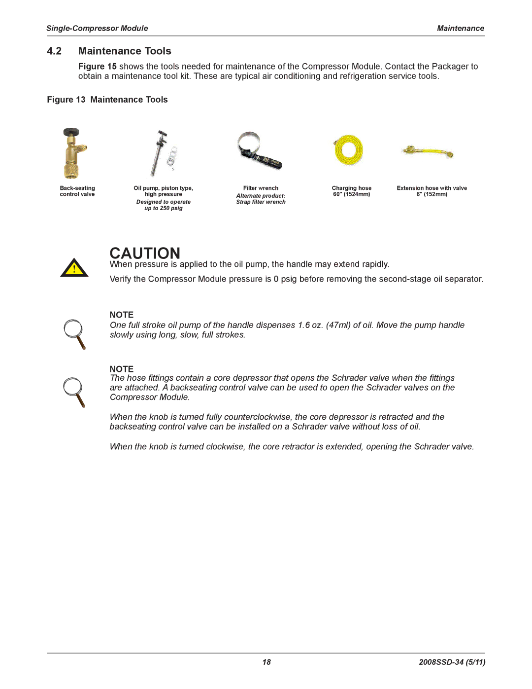
Figure 15 shows the tools needed for maintenance of the Compressor Module. Contact the Packager to obtain a maintenance tool kit. These are typical air conditioning and refrigeration service tools.
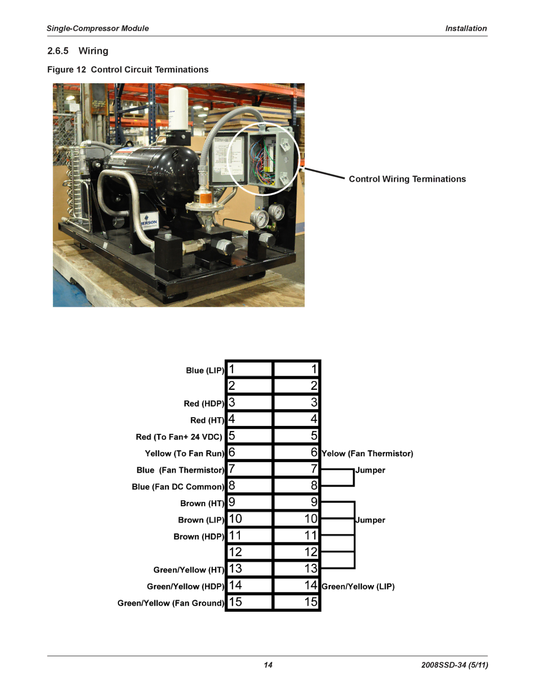
Figure 13 Maintenance Tools
Oil pump, piston type, | Filter wrench | Charging hose | Extension hose with valve | |
control valve | high pressure | Alternate product: | 60" (1524mm) | 6" (152mm) |
| Designed to operate | Strap filter wrench |
|
|
| up to 250 psig |
|
|
|
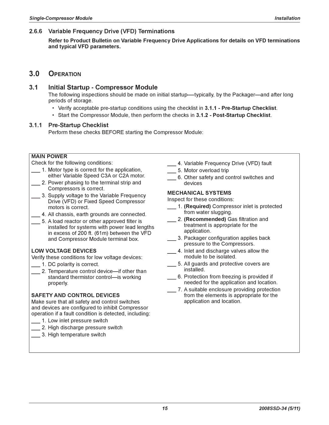
CAUTION
When pressure is applied to the oil pump, the handle may extend rapidly.
Verify the Compressor Module pressure is 0 psig before removing the
Note
One full stroke oil pump of the handle dispenses 1.6 oz. (47ml) of oil. Move the pump handle slowly using long, slow, full strokes.
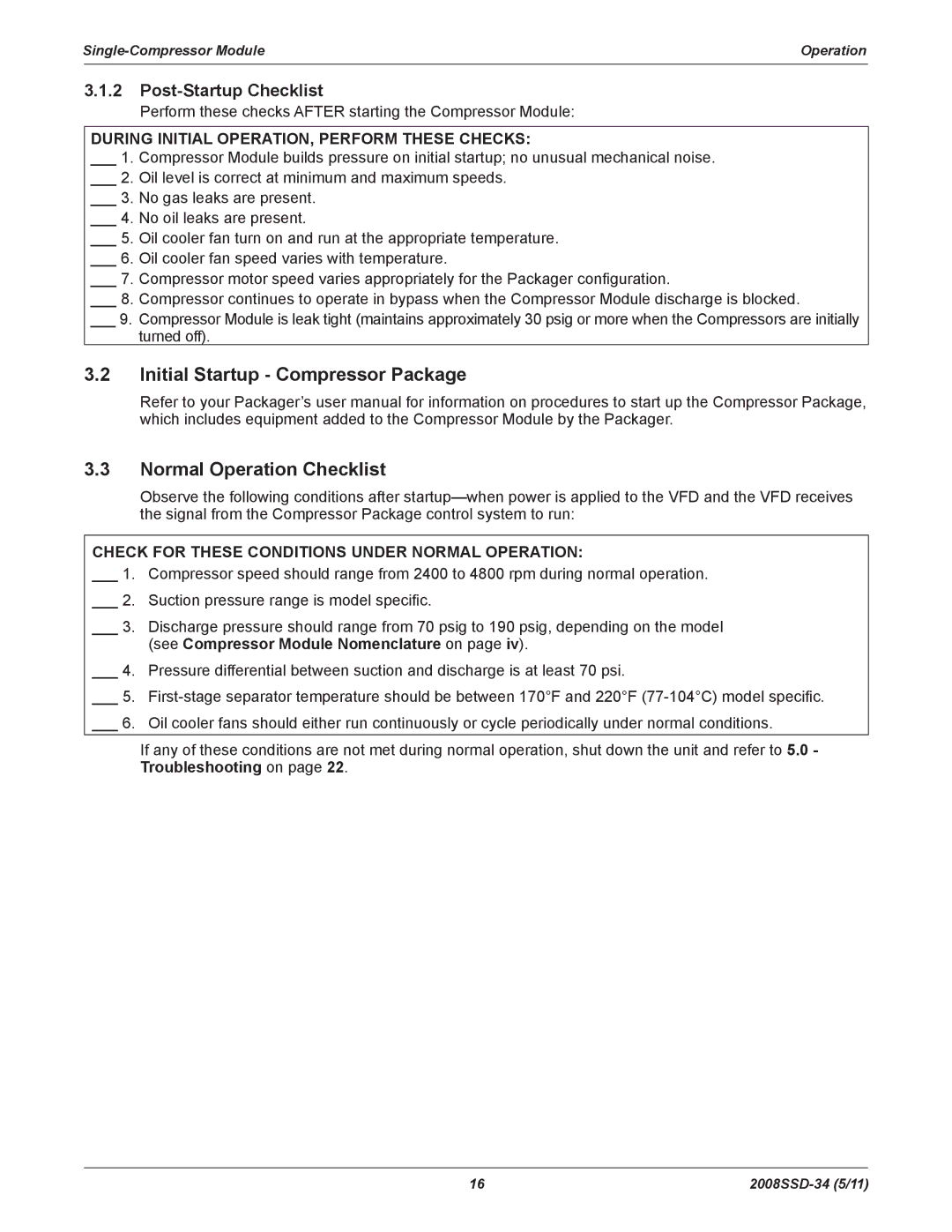
Note
The hose fittings contain a core depressor that opens the Schrader valve when the fittings are attached. A backseating control valve can be used to open the Schrader valves on the Compressor Module.
When the knob is turned fully counterclockwise, the core depressor is retracted and the backseating control valve can be installed on a Schrader valve without loss of oil.
When the knob is turned clockwise, the core retractor is extended, opening the Schrader valve.
18 |