Sears 113.21371 manual Assembly

Page 6

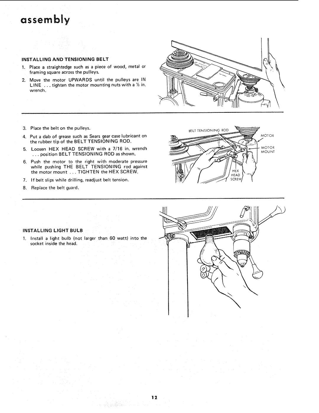
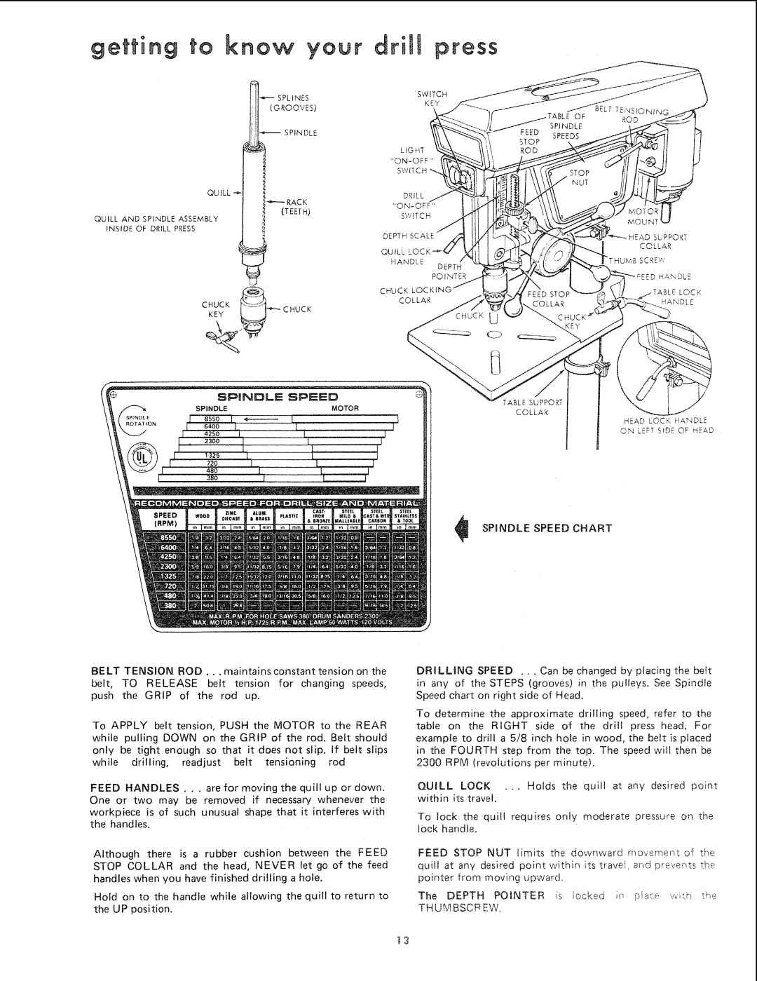
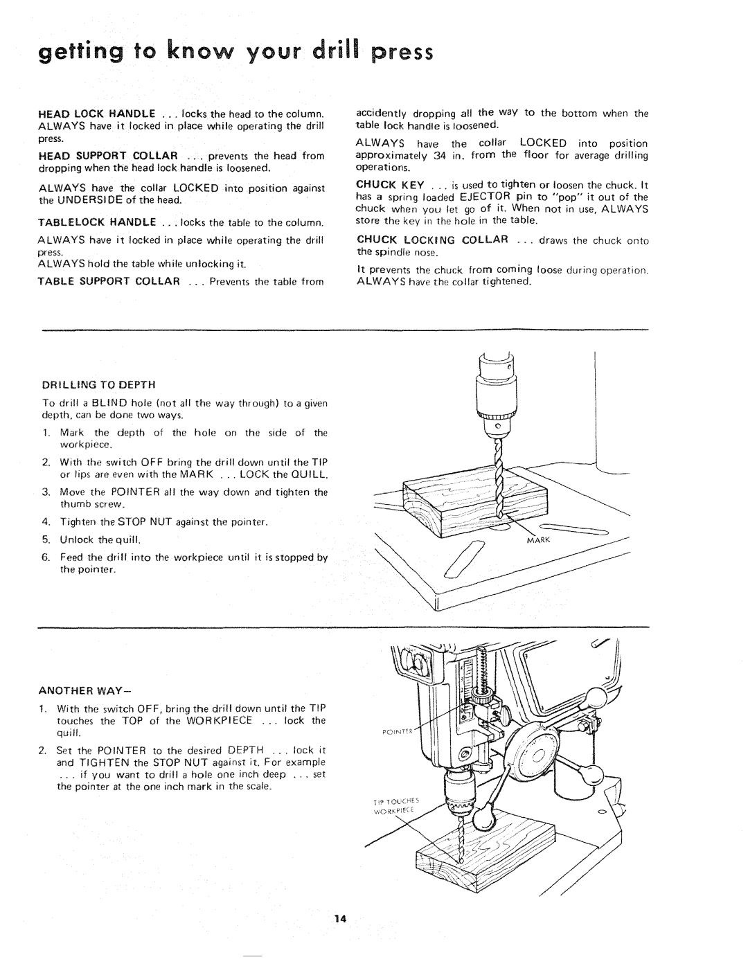
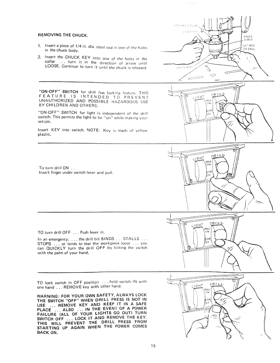
assembly

WARNING: FOR YOUR OWN SAFETY, NEVER CONNECT PLUG TO POWER SOURCE OUTLET UNTIL ALL ASSEMBLY STEPS ARE COMPLETED,

1.Unwind the power cord.

2.Make sure the quill lock handle is tight.

3.Stand on, the left side of the drill press and LOOSEN the HEAD LOCK HANDLE.

4.Raise the HEAD about HALF WAY up the column.

CAUTION: THE HEAD WEIGHS ABOUT 65 POUNDS DROPPING THE HEAD ACCIDENTLY COULD CAUSE PERSONAL INJURY OR DAMAGE THE DRILL PRESS.

5o TIGHTEN the Head Lock Handle.

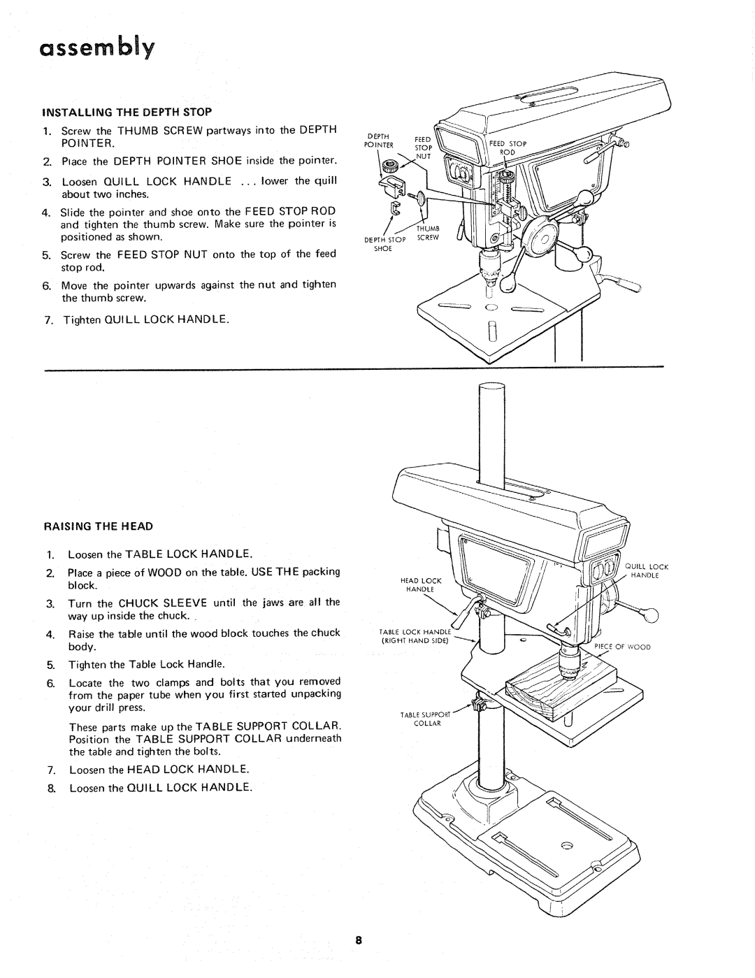
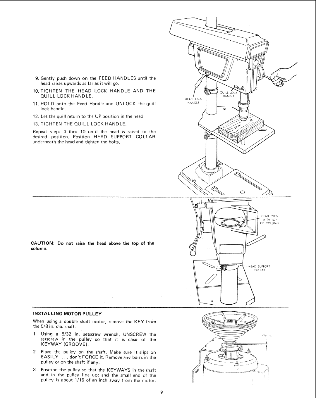
6. Position the HEAD-SUPPORT COLLAR underneath

the head and tighten the TWO BOLTS using a ½" wrench,

IN ORDER TO RAISE THE HEAD TO A HIGHER POSITION, IT WILL BE NECESSARY TO INSTALL SEVERAL PARTS.

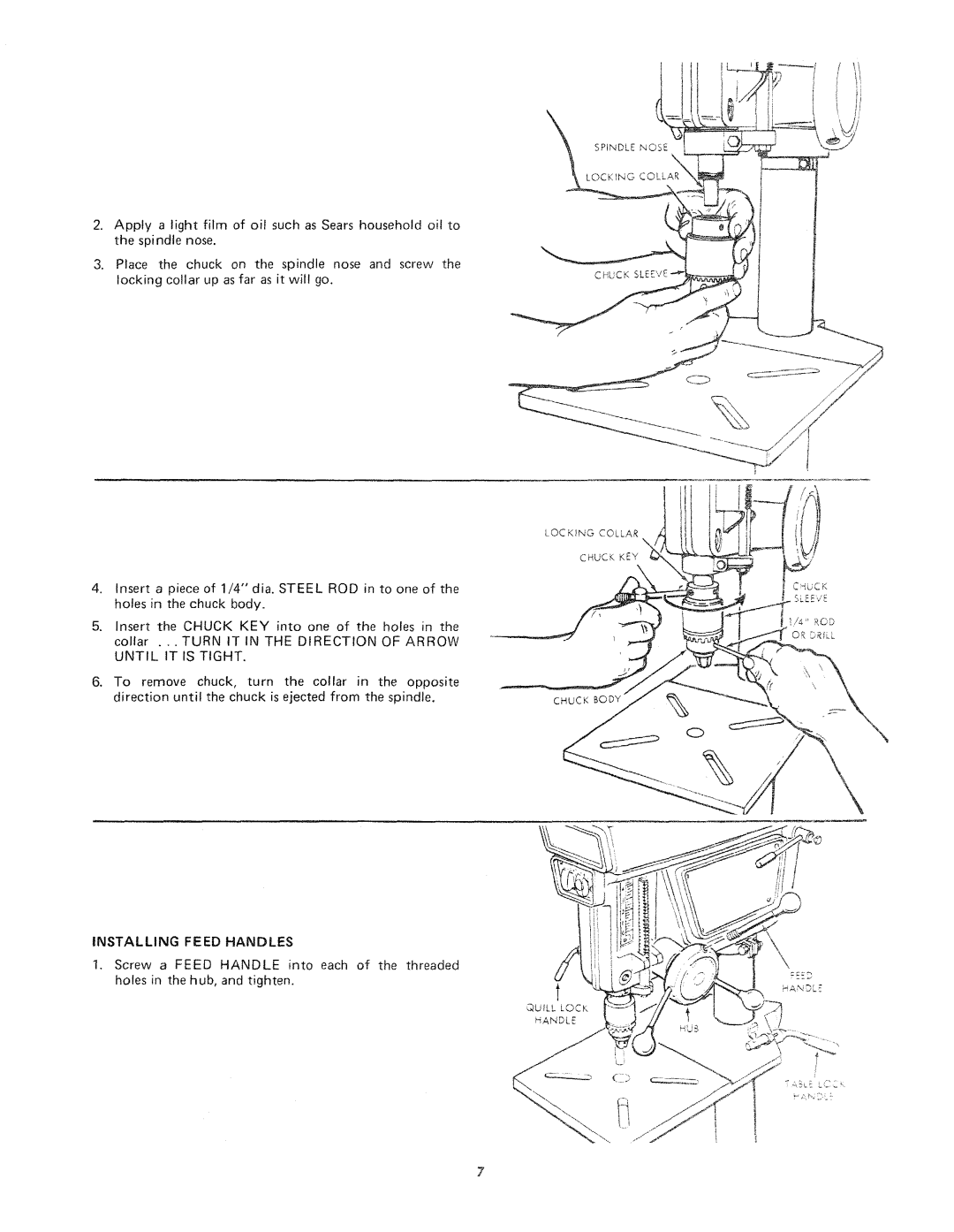
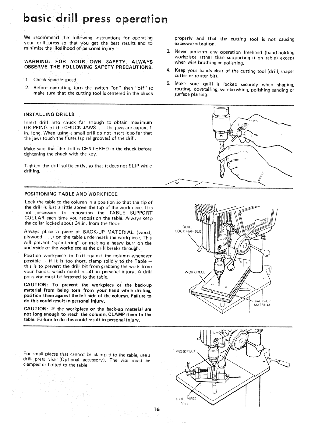
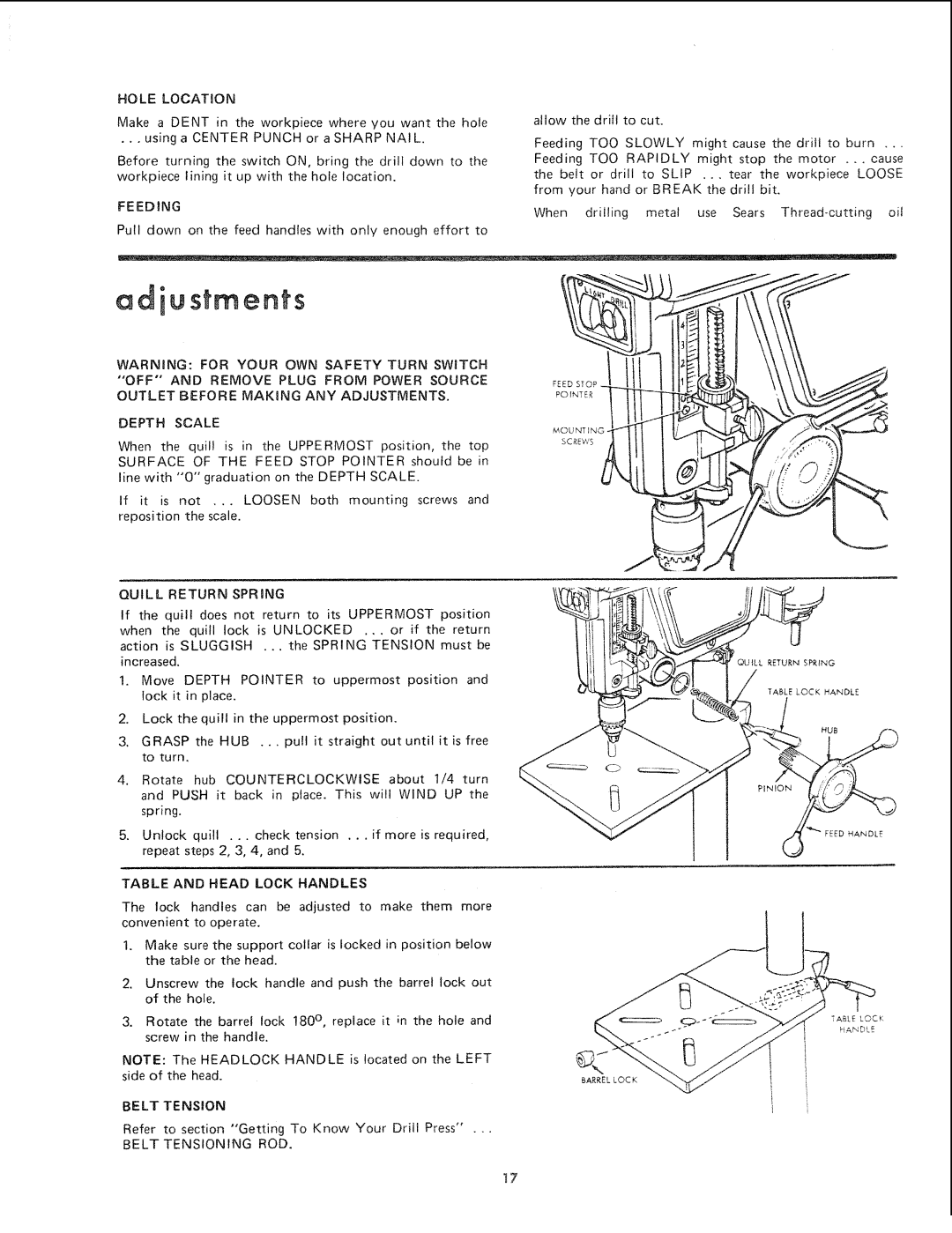
INSTALLING THE CHUCK

Clean out the TAPERED HOLE in the chuck; clean the spindle nose with a clean cloth Make sure there are no foreign particles sticking to the surfaces. The slightest piece of dirt on the spindle nose or in the chuck will prevent the chuck from seating properly. This will cause the drill to "wobble."

HEAD

LOCK HANDLE

HEAD SUPPORT

COLLAR

SPINDLE NOSE

6
Image 6
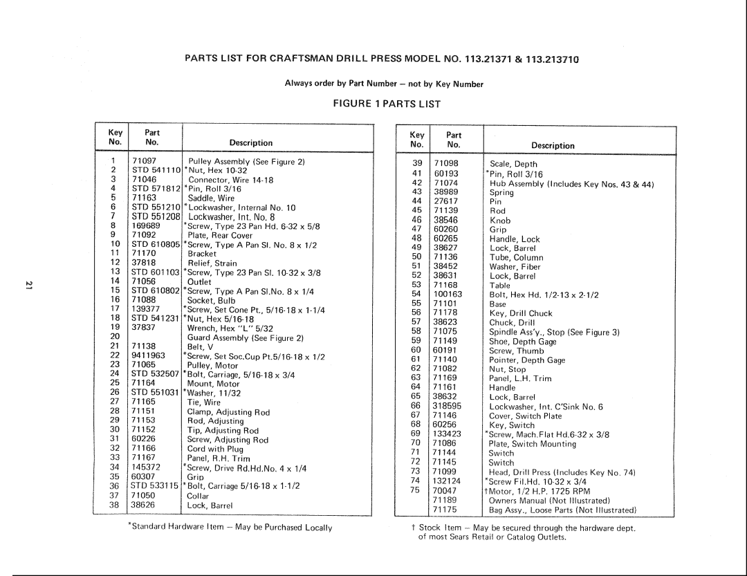
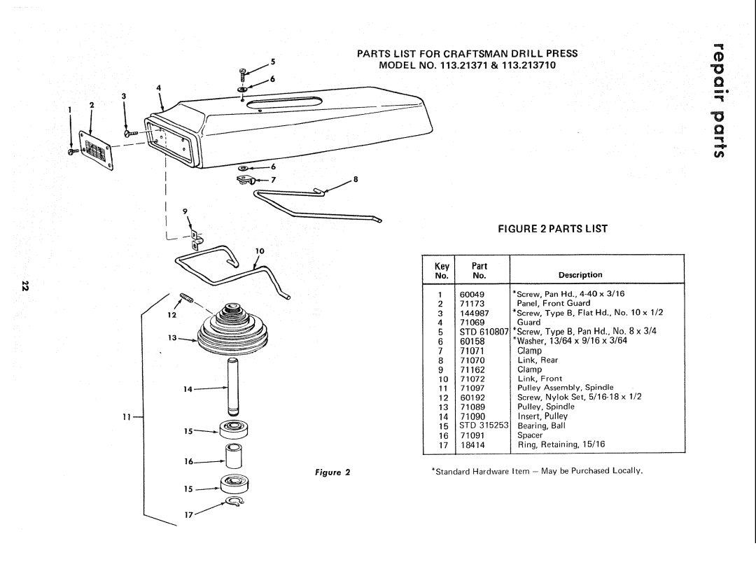
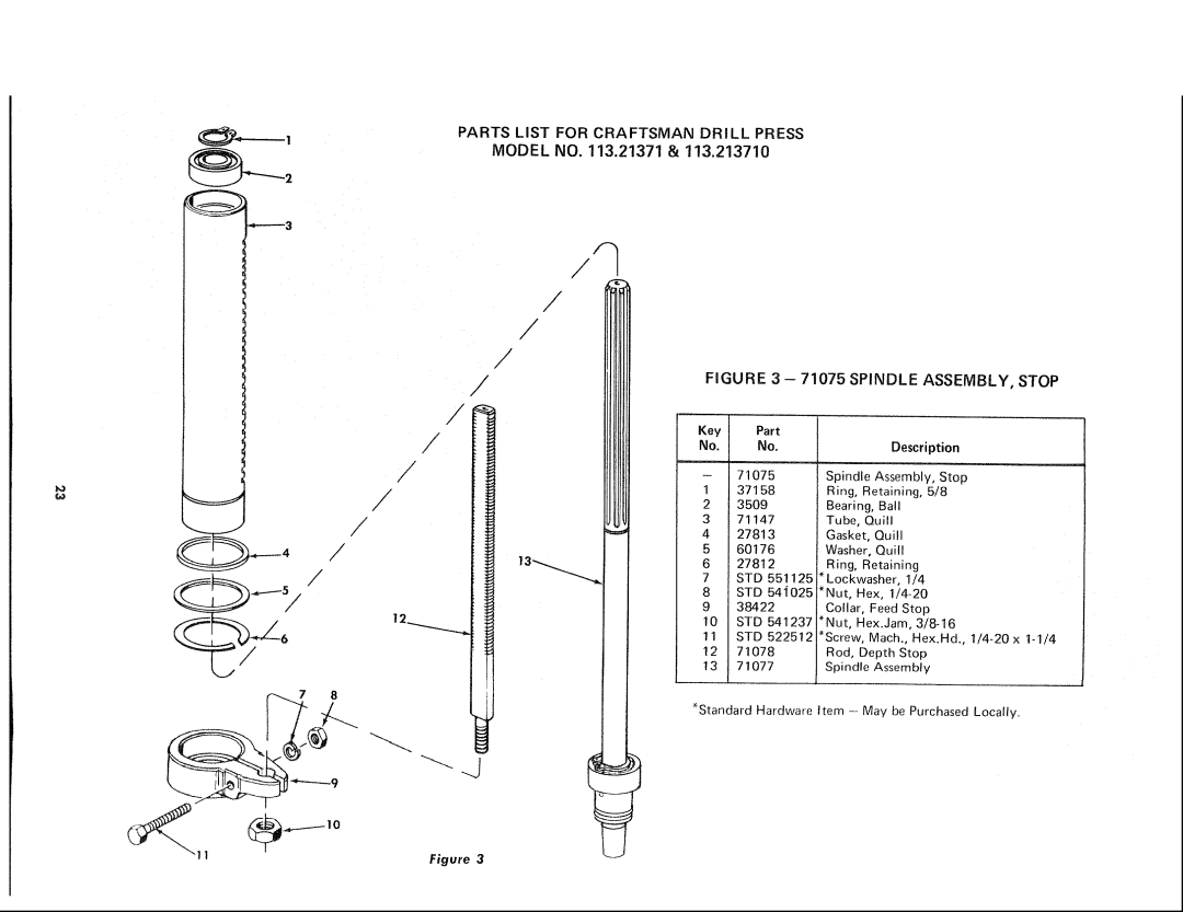
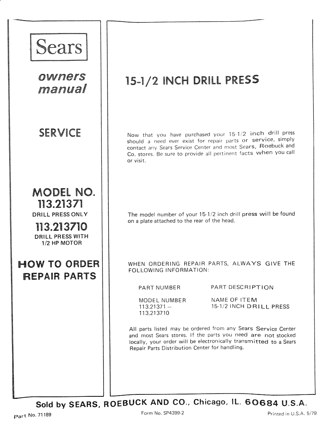
Contents Drill Press only Model no113.213710 DRI LL Press with HP MotorOr power tools Attempt to Operate Your Drill Press Until Additionam safety instructions for drill pressesFor Your OWN SAFETY, do not YOU have Read and Understand FollowingAdditional safety instructions for drill presses Unpacking checkingCutting Tool Connecting to Power Source OutletRPM Volts Catalog no Check Motor RotationAssembly Spindle Nose Locking Collar Chuck Chuck KEY Chuck Body Installing the Depth Stop Raising the HeadScrew the Thumb Screw partways into the Depth Pointer Tighten the Quill Lock Handle Installing Motor Pulley10, Tighten the Head Lock Handle and the Quill Lock Handle Keyway GrooveAssembty Mounting the MotorExcessive Tightness could Bend the Motor Mount Installing and Tensioning Belt GreaseBelt Tensioning ROD Spindle Speed Chart Getting Know Your Drill PressThumbscrew Tablelock Handle ,, locks the table to the column Getting to know your drill pressHead Lock Handle ... locks the head to the column Another WAYRemovingthe Chuck Back onOperation Observe the Following Safety PrecautionsInstalling Drills Positioning Table and WorkpieceAdiustments Hole LOCAT!ONBelt Tension Outlet Before Maintaining or Lubricating Your Drill Press Recommended accessoriesLubrication WheelTrouble shooting Outlet Before Trouble ShootingParts List for Craftsman Drill Press Model no .21371 STD Parts List for Craftsman Drill Press Model no .21371STD RPMParts List for Craftsman Drill Press KeyParts List for Craftsman Drill Press Model no .21371 71075 Spindle ASSEMBLY, StopModel Number Name 113.2!3710Part Inch Drill