Hobart 180 SD manual Dimensions And Weights, Specifications, Duty Cycle Chart

Page 14

2-3. Dimensions And Weights

A

B

Front

D

C


Dimensions


Height

21 in (533 mm)


Width

13-5/8 in (346 mm)


Length

22-1/8 in (562 mm)


A

21-5/16 in (541 mm)


B

13/16 in (21 mm)


C

12-7/16 in (316 mm)


D

1–1/16 in (27 mm)

E 4 Holes


E

1/2 (13 mm)


Weight


ST-802 259


210 lbs (95 kg)


2-4. Specifications


Rated Output at 40%

Rated Input,


Welding Amperage

Max. Open-Circuit

Mode

Duty Cycle

60 HZ, Single-Phase

KVA

KW

Range

Voltage


DC TIG

150 Amps at 16 Volts

230 V–38 A - (2)*

8.7 - (0.50)*

4.0 - (0.3)*

10–180

80


DC Stick

150 Amps at 26 Volts

230 V–42 A - (2)*

9.7 - (0.50)*

5.7 - (0.3)*

10–180

80


AC TIG

150 Amps at 16 Volts

230 V–67 A - (2)*

15.5 - (0.50)*

4.9 - (0.3)*

15–180

80


AC Stick

150 Amps at 26 Volts

230 V–53 A - (2)*

12.2 - (0.50)*

6.2 - (0.3)*

15–180

80


* () While idling.

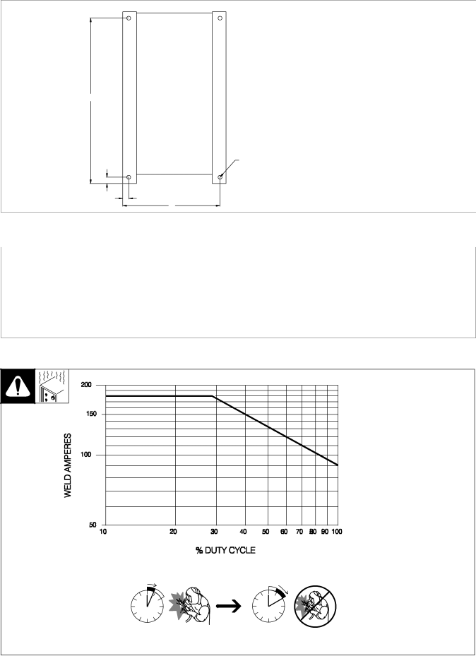
2-5. Duty Cycle Chart

40% Duty Cycle at 150 A AC/DC

Duty cycle is percentage of 10 minutes that unit can weld at rated load without overheating.

YExceeding duty cycle can damage unit and void warranty.

4 Minutes Welding

6 Minutes Resting

ST-188 276-A

OM-355 Page 10

Image 14
Contents Description OM-355Processes From Hobart to You Table of Contents Page Arc Welding Hazards Symbol UsageMarks a special safety message Electric Shock can killFlying Metal can injure eyes ARC Rays can burn eyes and skinWelding can cause fire or explosion Buildup of GAS can injure or killPrincipal Safety Standards EMF Information About PacemakersUN Choc É Lectrique peut tuer Signification des symbolesConsignes DE Securite Lire Avant Utilisation LES Fumé ES ET LES GAZ peuvent ê tre dangereuxLE Bruit peut affecter l’ouïe LE Soudage peut provoquer un incendie ou une explosionDES Particules Volantes peuvent blesser les yeux ’EMPLOI Excessif peut Risque D’INCENDIE OULA Chute DE L’APPAREIL peut blesser DES Organes Mobiles peuvent provoquer des blessuresConsignes relatives aux stimulateurs cardiaques Principales normes de sé curitéInformation sur les champs é lectromagné tiques Selecting a Location InstallationIncluded with Your Unit MovementDuty Cycle Chart Dimensions And WeightsSpecifications ARC Welding can cause Electromagnetic Interference Volt-Ampere CurvesWeld Output Terminals And Selecting Cable Sizes Socket Remote 14 ReceptacleShielding Gas Connections Necting to receptacleInput Voltage Electrical Service GuideConnecting Input Power Input Amperes at Rated OutputControls Output Selector SwitchOperation Select weld process Select polarity Select amperage Example Connect remote control see Section OM-355Example of Remote Amperage Control For TIG Gtaw Welding Select weld process Select polarityRemote Foot Control Typical TIG ConnectionsTypical Stick Connections ApplicationProcess and Material Thickness Guide Label Maintenance and TroubleshootingRoutine Maintenance Turn Off power before ad Adjusting Spark GapsTroubleshooting Justing spark gapsElectrical Diagram Circuit Diagram For Welding Power SourceHigh Frequency HF Welding Processes Using HFSources Of HF Radiation From Incorrect Installation Nonmetal Correct InstallationGround Wire Building Metal BuildingSelecting Tungsten Electrode Safety Information About TungstenSelecting and Preparing Tungsten Electrode Preparing Tungsten For DC Electrode Negative Dcen Welding Instead of thoriated. Tho Guidelines for TIG Welding GtawPositioning The Torch Mables awayWelding direction Form pool Tilt torch Torch Movement During WeldingTungsten Without Filler Rod Tungsten With Filler RodPositioning Torch Tungsten For Various Weld Joints Butt Weld And Stringer Bead Joint Lap Joint Corner JointOM-355 Stick Welding Smaw Guidelines Stick Welding ProcedureWeld current starts when electrode touches work- piece Striking an Arc Tapping Technique Electrode and Amperage Selection ChartStriking an Arc Scratch Start Technique Positioning Electrode Holder Poor Weld Bead CharacteristicsGood Weld Bead Characteristics 9090 End View of Work AngleConditions That Affect Weld Bead Shape Electrode Movement During WeldingTee Joint Butt JointsLap Joint 16 in 1.6 mm Tack WeldsWeld Test Troubleshooting PorosityTroubleshooting Excessive Spatter Possible Causes Corrective ActionsTroubleshooting Excessive Penetration Troubleshooting Incomplete FusionTroubleshooting Lack Of Penetration Troubleshooting Distortion Troubleshooting Burn-ThroughTroubleshooting Waviness Of Bead Parts List Main AssemblyDia Part Description Quantity Mkgs 043 Panel, Front w/Components Page Page Page Service SupportCall Contact your Distributor forHobart Welding Products