Grizzly G0756 owner manual Safety Instructions for Machinery

Page 9

SECTION 1: SAFETY

for your Own Safety, Read Instruction Manual before Operating This Machine

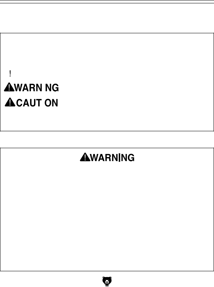
The purpose of safety symbols is to attract your attention to possible hazardous conditions. This manual uses a series of symbols and signal words intended to convey the level of impor- tance of the safety messages. The progression of symbols is described below. Remember that safety messages by themselves do not eliminate danger and are not a substitute for proper accident prevention measures. Always use common sense and good judgment.


Indicates an imminently hazardous situation which, if not avoided,


WILL result in death or serious injury.


Indicates a potentially hazardous situation which, if not avoided,


cOULD result in death or serious injury.


Indicates a potentially hazardous situation which, if not avoided,


MAy result in minor or moderate injury. It may also be used to alert


against unsafe practices.

NOTICE

This symbol is used to alert the user to useful information about

proper operation of the machine.

Safety Instructions for Machinery

OWNER’S MANUAL. read and understand this owner’s manual BeFore using machine.

TRAINED OPERATORS ONLy. untrained oper- ators have a higher risk of being hurt or killed. only allow trained/supervised people to use this machine. When machine is not being used, dis- connect power, remove switch keys, or lock-out machine to prevent unauthorized use—especially around children. Make workshop kid proof!

DANGEROUS ENvIRONMENTS. do not use machinery in areas that are wet, cluttered, or have poor lighting. operating machinery in these areas greatly increases the risk of accidents and injury.

MENTAL ALERTNESS REQUIRED. Full mental alertness is required for safe operation of machin- ery. never operate under the influence of drugs or alcohol, when tired, or when distracted.

ELEcTRIcAL EQUIPMENT INJURy RISKS. you can be shocked, burned, or killed by touching live electrical components or improperly grounded machinery. to reduce this risk, only allow qualified service personnel to do electrical installation or repair work, and always disconnect power before accessing or exposing electrical equipment.

DIScONNEcT POWER fIRST. Always discon- nect machine from power supply BeFore making adjustments, changing tooling, or servicing machine. this prevents an injury risk from unintended startup or contact with live electrical components.

EyE PROTEcTION. Always wear Ansi-approved safety glasses or a face shield when operating or observing machinery to reduce the risk of eye injury or blindness from flying particles. everyday eyeglasses are not approved safety glasses.

Model G0756 (Mfg. Since 2/13)

-7-

Image 9
Contents Model G0756 Industrial Drill Press Page Table of Contents Introduction Machine Description Manual AccuracyContact Info Identification Control Panel Machine Data Sheet Main Specifications Operation Info Safety Instructions for Machinery SafetyPage Safety for Drill Presses Availability Power SupplyFull-Load Current Rating Circuit Requirements forExtension Cords Grounding InstructionsMinimum Gauge Size 14 AWG 50 ftNeeded for Setup SetupUnpackingInventory Inventory see Figure QtyCleanup Before cleaning, gather the followingBasic steps for removing rust preventative Site Considerations Lifting & Placing Anchoring to FloorAnchoring to Concrete Floors Arbor/Chuck Assembly Initial LubricationTo connect the drill chuck with the arbor To connect the power cord to the machine Power ConnectionTest Run Master power switch Model G0756 Mfg. Since 2/13Emergency To test the coolant system Test Coolant SystemSpindle Break-In To perform the spindle break-in procedureTooling Installation Removal OperationsOperations Overview Installing Tapered Tooling Removing Tooling with Automatic DriftRemoving Tooling Manually Table Positioning Depth StopRaising/Lowering Table Rotating TableTo determine the needed RPM Selecting SpindleDrilling Mode Automatic Power Downfeed Tapping Mode Coolant System To use tapping modeTo operate the coolant system G1075-52-PC. Clamping Kit ACcESSORIESH7616 H7617 G3658-Titanium Drill BitsH8262-1⁄2 x MT#4 Keyless Chuck with Integral Shank H7819-Drill & Tap HSS 24 pc. SetMaintenance Cleaning ProtectingSchedule Headstock Lubrication LubricationTo change oil in headstock Oil Flow Sight GlassBall Oilers Changing CoolantTroubleshooting ServiceSymptom Possible Cause Possible Solution Motor & ElectricalDrill Press Operations Replacing Lamp Bulb Torque LimiterTo replace the bulb in the work lamp Wiring Safety Instructions WiringComponent Location Index Wiring OverviewElectric Clutch Wiring Power Connection WiringHot 220 VAC PlugSpindle motor wiring Motor & Pump WiringViewed from behind Control Panel & Limit Switches QM5 QM3 QM2 QM1 Electrical Panel WiringElectrical wiring panel Model G0756 Mfg. Since 2/13 Electrical Wiring Panel PhotoTable Support & Coolant Breakdown PartsDescription Table Support & Coolant Parts ListGearbox Breakdown Gearbox Breakdown Gearbox Parts List Spindle Feed Breakdown Spindle Feed Parts List Headstock Breakdown Headstock Breakdown Headstock Parts List Electrical Parts Breakdown Description Electrical Parts List506 502 503 501 508 509 507 510 504 511 505 512 513 Labels & CosmeticsComments Warranty CardBOX BELLINGHAM, WA Grizzly INDUSTRIAL, INCWarranty & Returns