HP 6000 Software Configuration, Overview, LPT Parallel Port Driver Installation Instructions

Page 17

Chapter 1 - Installation and Configuration

Software Configuration

Connecting the controller and installing the Parallel Port drivers (Pre-2005 Parallel interface units ONLY)

Installing the Userport.Sys Driver (Required for Windows NT, 2000, And XP Professional users)

NOTE: If you recieved a Pre-Configured Laptop From us, the Steps below have already been performed -you will ony need to follow the steps below if you are Re-Installing the Operating System.

Overview

This guide will Assist you with the Required Changes that must me made to windows XP Professional before the soft- ware and platform will function correctly

Note about Windows XP: The Antenna Measurement Software Has only been tested and is only supported on the Professional version of Microsoft Windows XP .

(LPT) Parallel Port Driver Installation Instructions:

Step 1:

The software installation has placed a Folder named “UserPort” located in the “C:\DAMS” Folder.

The userport.sys file allows the Windows XP operating system to communicate with the parallel port and control the platform. Follow the instructions bellow to install the Userport.sys Driver.

1. Go to the “C:\dams\userport\” folder and copy the “Userport.sys” file to the windows system32\Drivers Folder. it is usually located in “C:\windows\system32\drivers”

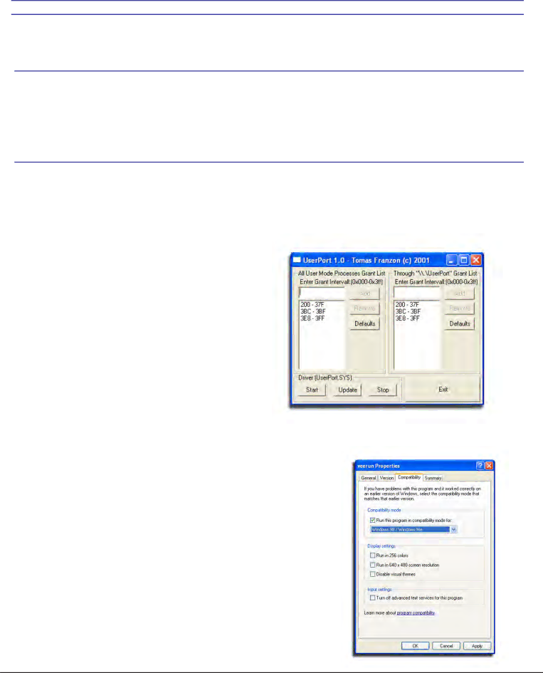
2. Run the Userport.Exe program as shown at right and Select the I/O range you wish to use and Press Start. (if you do not know which ports to leave open just press start and the defaults will be used)

--For additional Information Please read the Userport.PDF located in the Userport Folder ---

Step 2:

Setting the Compatibility mode for VEE Runtime 6.0 (XP PRO ONLY!)

In order for the software to work absolutly correctly we reccomend setting the Windows XP compatibility mode to Windows 98/Me Mode for less chances of errors caused by the windows XP Kernel.

1. Open “My Computer” located in the Start Menu

2. Open your “C:” Drive

3. Double click on the “Program Files” Folder

4. Double Click “Agilent” then double click the “Vee Pro Runtime” Folder.

17

Image 17
Contents Desktop Antenna Measurement System Model Page Table Of Contents Page Page Introduction Key Features FeaturesMinimum System Requirements RequirementsPlatform Controller rear view Platform Controller top view USB Port Platform Controller UnitControl Unit Front View Control Unit Side View Parallel Port Platform Controller UnitPage Unpacking the System Package ContentsVertical Assembly Tripod AssemblyTripod and Elevation Unit Assembly Connecting the platform and vertical actuator Platform AssemblyAttaching the cables Cable ConnectionsInstalling the Software Software and Hardware InstallationLPT Parallel Port Driver Installation Instructions Software ConfigurationOverview StepSignal Generator Name setting Network Analyzer Name settingSpectrum Analyzer Name setting Power MeterTripod Compatibility Information Platform Positioning Test System TestSpecial Installation Notes Installation NotesScreen Sleepers and Power Saving options Other Running ApplicationsPage Chapter Measurement Settings Instrument Selection and Settings Measurement SettingsSource Instrument Settings Only instrument Receive Instrument -Power Meter SettingsMeasurement Settings Azimuth setup Measurement SettingsElevation setup Platform Settings and CalibrationPower Sensor Calibration Calibration SettingsCalibration Settings Scalar Calibration Measurement Controls Measurement ControlsGraphical Status Displays Measurement Status and DisplaysMeaurement Status and Displays Measurement Status window Data Processing Introduction Data ProcessingActive Register Data RegistersData Processing Dynamic Amplitude Plot Vertical Swing Correction Measurement CalculatorDipole Link Simulator Page Performing a Scalar Calibration System CalibrationMaking a basic Vertical/Elevation Measurement Basic MeasurementsMaking a basic Horizontal/Azimuth Measurement Performing an AZ/EL Scan Measurement Az/El Scan MeasurementsPage Introduction Data Processing ScreenshotData Processing Feature To Print a Plot Viewing and working with measurements in 3DTo Label a Plot To Export as BMP Image File- Click File ExportDynamic Amplitude Plot Screenshot Viewing and working with the Dynamic Amplitude PlotInstructions Polar Plot Screenshot Viewing and working with the Polar Plot displayRegister Math / Calculator Screenshot Using the Measurement Calculator / Register Math FunctionUnderstanding the Register Math Functions Math FunctionsLinMag LogMag LinearMeasurement Export Process Data Processing FeatureExporting Data Measurement Export Process Contd Using the Dipole and Isotropic Link Calculator Using the Dipole and Isotropic Link Calculator Contd Group Delay Screenshot Page Page Troubleshooting Troubleshooting and ServiceTroubleshooting Operation Service and Contact Info
Related manuals
Manual 61 pages 62.96 Kb