TCONT802AS32DA TOUCH SCREEN AND TCONT803AS32DA TOUCH SCREEN WITH DEHUMIDIFICATION
|
|
|
|
| HEAT PUMP |
|
|
| ||
|
| Y2 |
|
|
| 1 |
| RC |
| |
|
| F |
|
|
|
| R |
| ||
|
|
|
|
|
|
|
| |||
|
| X2 |
|
|
|
|
| O |
| |
|
| W1 |
|
|
|
|
| Y |
| |
| 2 | S1 |
|
|
|
|
| G |
| |
|
|
|
|
|
|
|
|
| ||
| T | S2 |
|
|
|
|
| B |
| |
|
|
|
|
|
|
|
|
| ||
| 1 |
|
|
|
|
|
|
|
| |
|
|
|
|
|
|
|
|
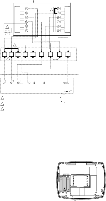
| VARIABLE | |
R | BK | O | G | YLO | Y | W1 | W2 | B/C | SPEED | |
TWO STAGE | ||||||||||
|
|
|
|
|
|
|
|
| ||
| 3 |
|
|
|
|
|
|
| FURNACE | |
|
|
|
|
|
|
|
|
| ||
|
|
|
|
|
| INDOOR |
|
|
| |
|
|
|
|
|
| OUTDOOR |
|
|
| |
R | Y2 | Y1 | O | X2/BK | BR(T) |
| B | 16 SEER | ||
| HEAT PUMP | |||||||||
|
|
|
|
|
|
|
|
| ||
|
|
|
|
|
|
|
|
| O.D. SECTION | |
|
|
|
|
|
|
|
|
| (TWO STEP) | |
|
|
|
|
|
|
|
|
|
|
| TO POWER SUPPLY |
| (3 PH |
|
| ||
1 | FACTORY INSTALLED JUMPER. | PER LOCAL CODES |
| ONLY) |
| |||
|
|
|
|
|
| |||
2 | OUTDOOR REMOTE SENSOR. WIRES MUST HAVE A |
|
|
|
|
|
| |
|
|
|
|
|
| |||
|
|
|
|
|
| |||
CABLE SEPARATE FROM THE THERMOSTAT CABLE. |
|
|
|
|
|
| ||
|
|
|
|
|
|
| ||
3 | REMOVE / CUT JUMPER FROM R TO BK. |
| M24203 |
| ||||
|
|
|
|
|
|
| ||
Fig. 15. Typical hookup of multistage two-step scroll heat pump with two stage variable speed gas furnace
(3H/2C heat pump).
Powering the Comfort Control
The Comfort Control can be powered with 24 Vac.
24 Vac Common Power (Recommended)
Wire the common side of the transformer to the B screw of the comfort control wallplate. When installing in a single transformer system, keep the jumper wire between the R and Rc screws. When installing in a
Battery Power (Optional)
![]() CAUTION
CAUTION
Equipment or Property Damage Hazard. Using battery power only may not provide adequate power to comfort control and can cause damage during freezing conditions. Connect the 24 Vac Common (B) wire from the system transformer to the comfort control for proper operation when the battery power is drained.
Three AAA alkaline batteries can be used to power the comfort control for armchair programming only. To prevent the comfort control and heating/cooling system from shutting down due to lack of battery power, it is not recommended that the comfort control be solely powered with the three AAA batteries during normal system operation. When using batteries, make sure positive and negative terminals are oriented correctly, as marked on the device. See Fig. 16.
BATTERIES (3) | M19918 |
Fig. 16. Installing batteries on comfort control back.
Pub. No. |
|
8 |