Kenmore 300 Series, 300 Series warranty Procedure for Removing Error Code from Faceplate

Page 35

Service Tech Information

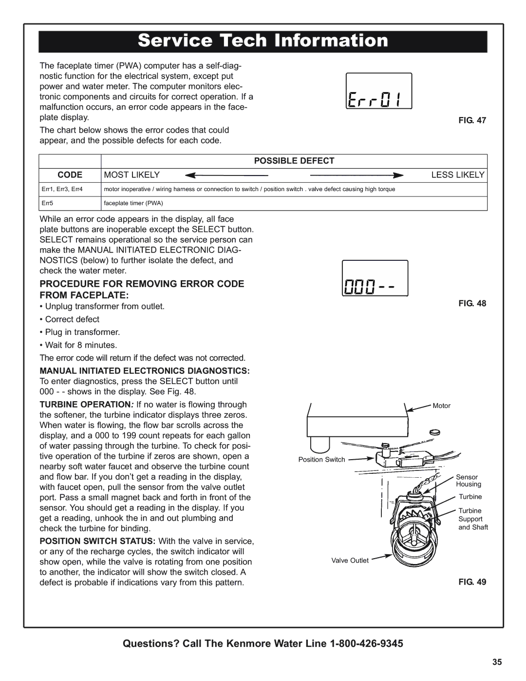
The faceplate timer (PWA) computer has a self-diag-


nostic function for the electrical system, except put


power and water meter. The computer monitors elec-


tronic components and circuits for correct operation. If a


malfunction occurs, an error code appears in the face-


plate display.


FIG. 47


The chart below shows the error codes that could


appear, and the possible defects for each code.


POSSIBLE DEFECT


CODE

MOST LIKELY


LESS LIKELY


Err1, Err3, Err4

motor inoperative / wiring harness or connection to switch / position switch . valve defect causing high torque


Err5

faceplate timer (PWA)


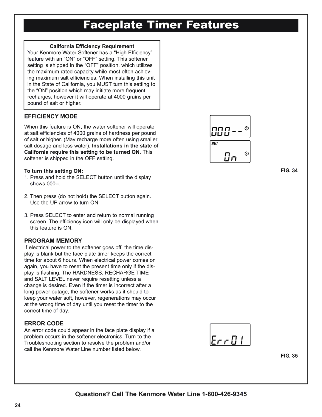
While an error code appears in the display, all face plate buttons are inoperable except the SELECT button. SELECT remains operational so the service person can make the MANUAL INITIATED ELECTRONIC DIAG- NOSTICS (below) to further isolate the defect, and check the water meter.

PROCEDURE FOR REMOVING ERROR CODE FROM FACEPLATE:

Unplug transformer from outlet.

Correct defect

Plug in transformer.

Wait for 8 minutes.

The error code will return if the defect was not corrected.

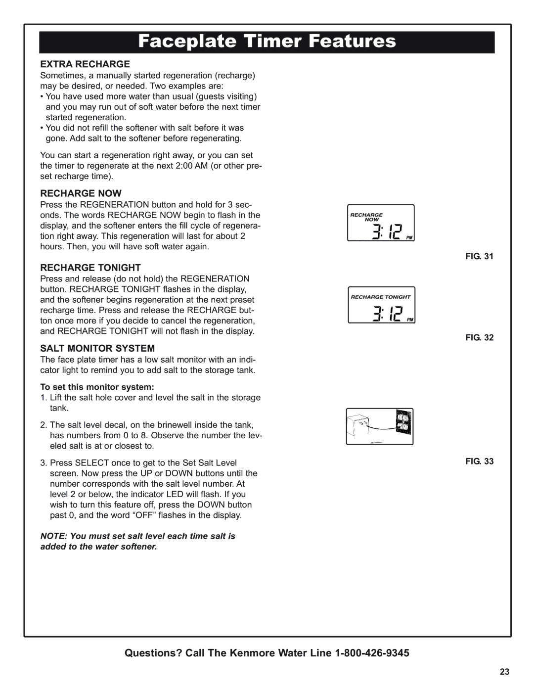
MANUAL INITIATED ELECTRONICS DIAGNOSTICS: To enter diagnostics, press the SELECT button until 000 - - shows in the display. See Fig. 48.

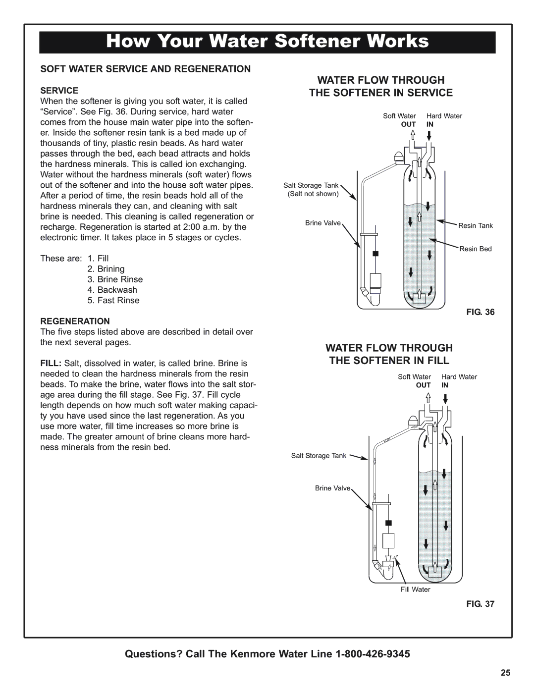
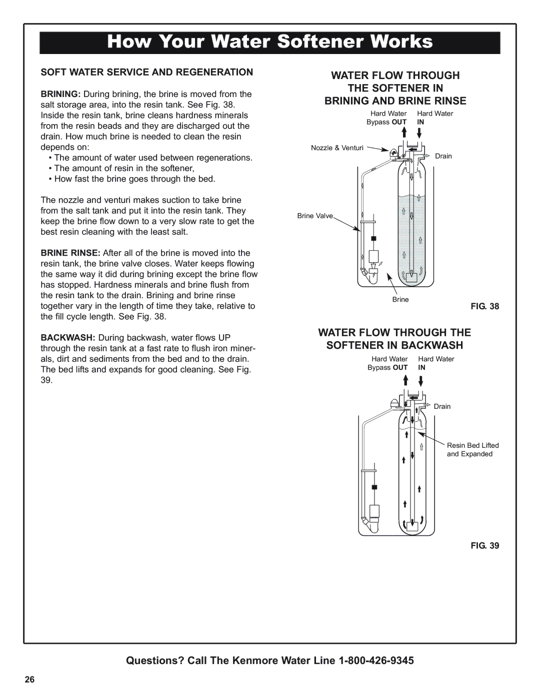
TURBINE OPERATION: If no water is flowing through the softener, the turbine indicator displays three zeros. When water is flowing, the flow bar scrolls across the display, and a 000 to 199 count repeats for each gallon of water passing through the turbine. To check for posi- tive operation of the turbine if zeros are shown, open a nearby soft water faucet and observe the turbine count and flow bar. If you don’t get a reading in the display, with faucet open, pull the sensor from the valve outlet port. Pass a small magnet back and forth in front of the sensor. You should get a reading in the display. If you get a reading, unhook the in and out plumbing and check the turbine for binding.

POSITION SWITCH STATUS: With the valve in service, or any of the recharge cycles, the switch indicator will show open, while the valve is rotating from one position to another, the indicator will show the switch closed. A defect is probable if indications vary from this pattern.

FIG. 48

Motor

Position Switch

Sensor

Housing

Turbine

Turbine

Support

and Shaft

Valve Outlet

FIG. 49

Questions? Call The Kenmore Water Line 1-800-426-9345

35

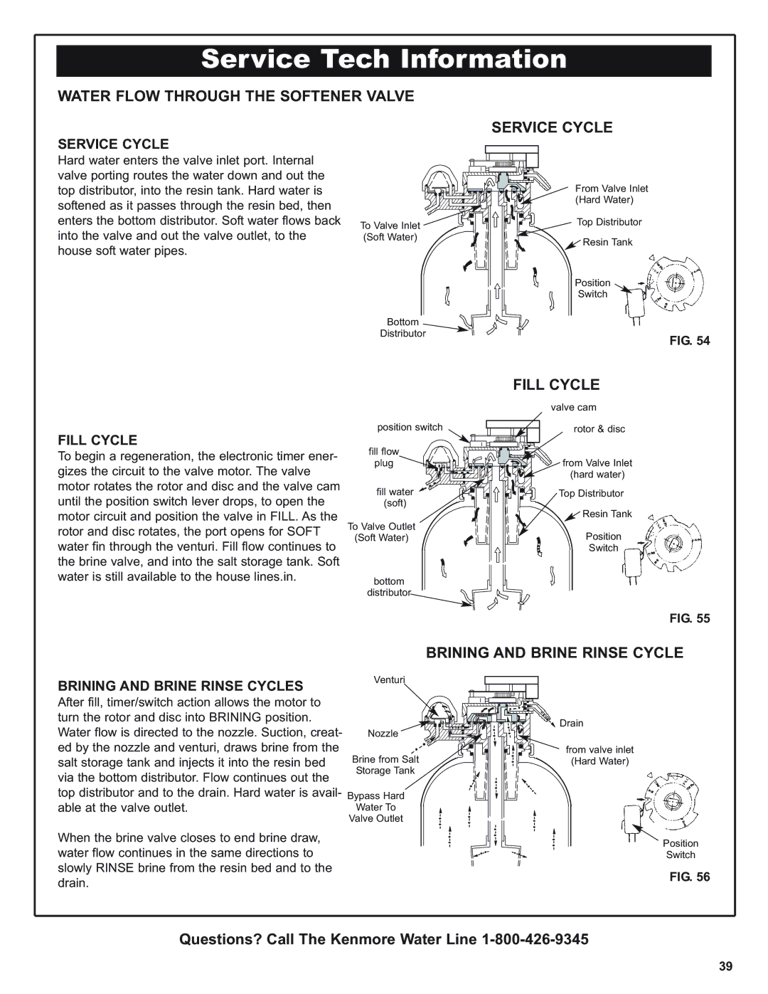
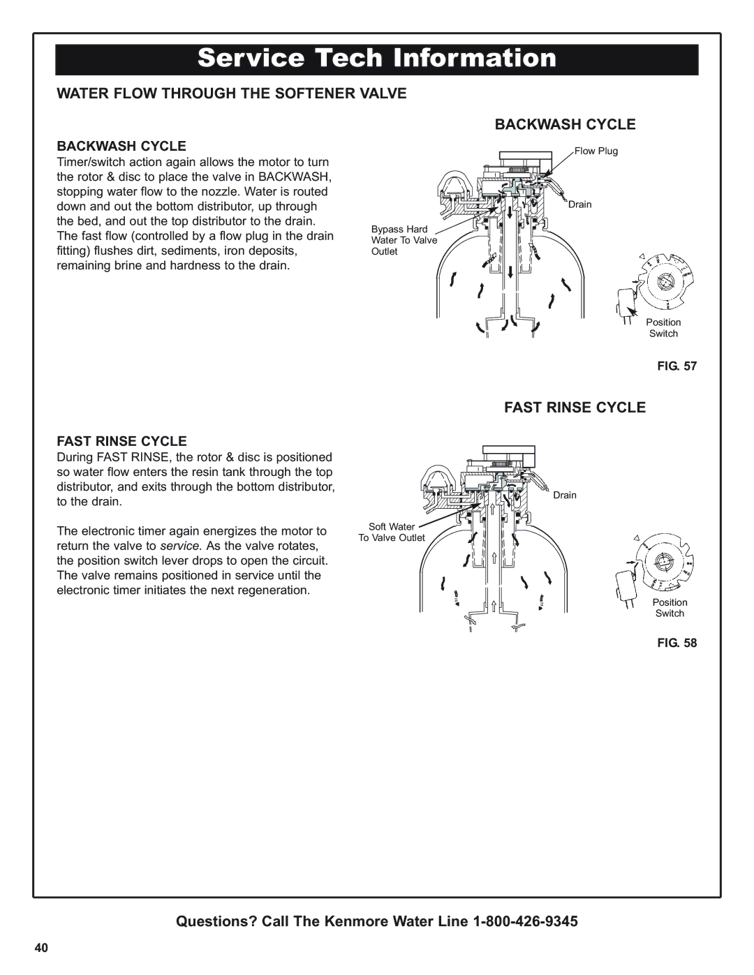
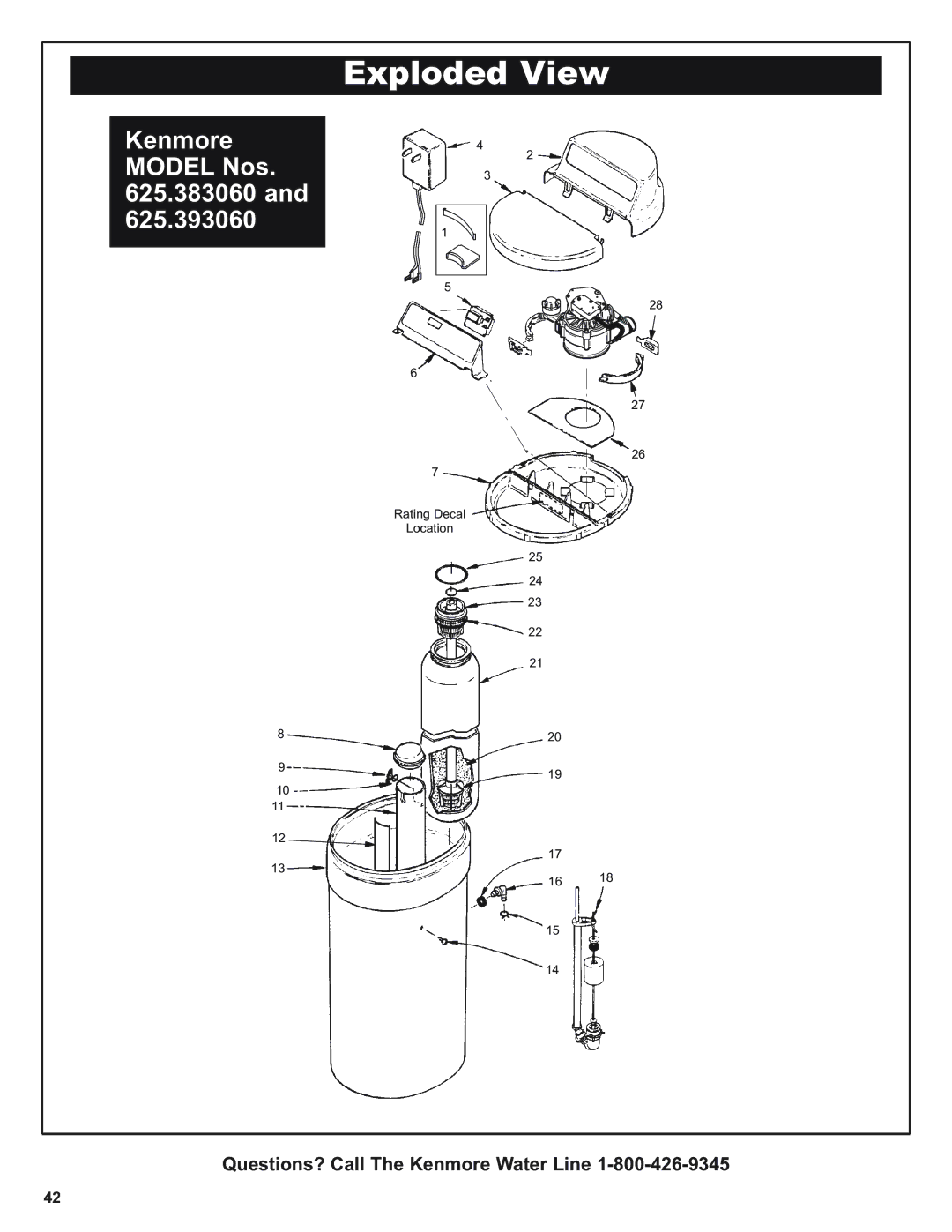
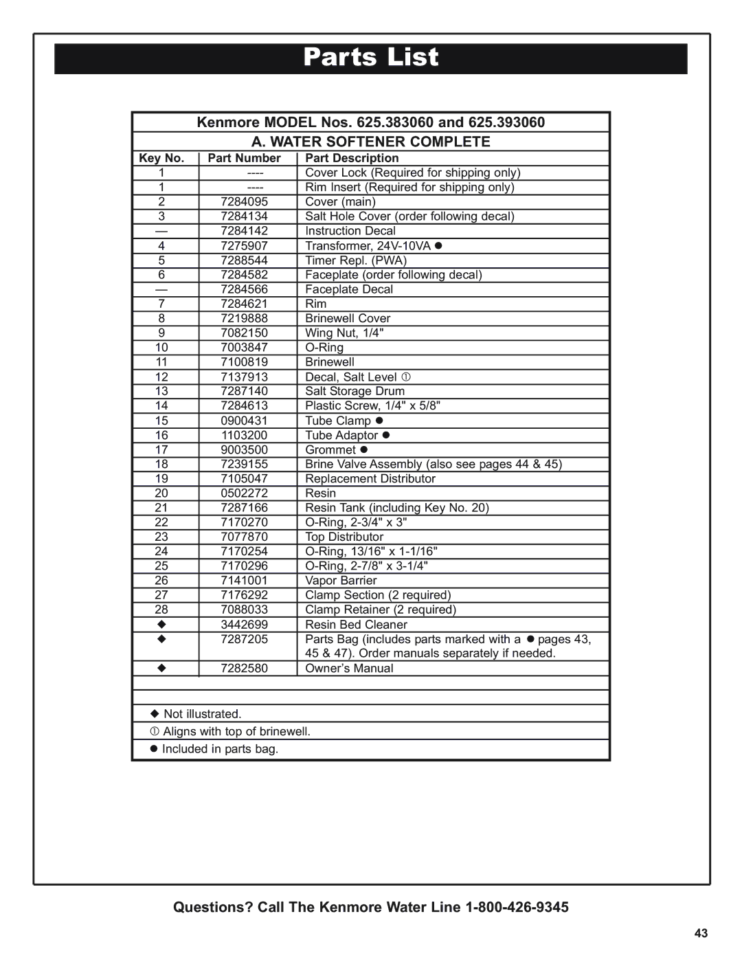
Image 35
Contents Save this Manual Repair or Parts ? Call toll freeDisclaimer of implied warranties limitation of remedies ONE Year Limited Warranty on Water SoftenerTEN Year Limited Warranty Against Leaks Facts and Figures to Keep Table of ContentsSafety Guides Inspect Shipment Unpack and Check Your CartonParts Descriptions Small PartsTools Needed Plan Your InstallationProper Order to Install Water Treating Equipment Plan Your InstallationWhere to Install the Water Softener Typical InstallationDraw in Your Pipes and Fittings Suggested Slab Foundation InstallationPIPE, FITTINGS, Other Materials Needed OUTBefore Installing Checks & Tests Read Before Beginning InstallationBypass Valve Install Plastic Bypass ValveAssemble Inlet Outlet ADAPTORS, or Plastic Bypass Valve Valve Bypass Install 3-Valve BypassInstalling Holding Clips Installing 3 Valve Bypass and PipesPosition Softener Into Place Locate Water Softener and Connect PipesMove Softener Into Place Typical Soldering ConnectionsConnect Salt Tank Overflow Tubing Connect Valve and Salt Tank DrainsConnect the Valve Drain Hose Leak Test Leak TestHouse Main Water Shutoff Valves Single BypassCold Water Pipe Grounding Water Meter Jumper WireConnecting Transformer Electrical RequirementsRestart the Water Heater Install Covers and Restart Water HeaterInstall Covers Install CoversSET Present Time of DAY Program The TimerProgram the Timer SET Salt Level SET Water Hardness NumberSET Regeneration Time Sanitize Your Water Softener AS Follows Sanitize The Water SoftenerSanitize the Water Softener Water Softening Salt with Iron Removing Additives Adding Salt To The Storage TankAdding Salt to the Storage Tank Check List Check List of STEP-BY-STEP Guides to InstallRecharge Tonight Faceplate Timer FeaturesExtra Recharge Recharge NOWProgram Memory Efficiency ModeError Code To turn this setting onWater Flow Through Softener in Fill Water Flow Through Softener in ServiceSoft Water Service and Regeneration How Your Water Softener WorksWater Flow Through Softener in Backwash Water Flow Through Softener Brining and Brine RinseElectronics Water Flow Through Softener Fast RinseAutomatic Bypass Salt Bridge Care Of Your Water SoftenerSalt Bridge Nozzle & Venturi Keeping the Water Softener CleanIron from Resin BED Protect the Water Softener from Freezing Drain ALL Water from SoftenerChecklist to Help YOU Save Money Problem Cause CorrectionInches SpecificationsModel 38306 Timer Code S Model 39306 Timer Code S Bypass ValvesOther Specifications Always Make These Initial Checks First Service Tech InformationWiring Schematic FaceplatePossible Defect Code Procedure for Removing Error Code from FaceplateModel Troubleshooting Valve Position IndicatorsTimer PWA Replacement Other InformationCycle Flow Rates Gallons PER MIN Brine Valve Float SettingManual Advance Regeneration Check To Relieve Pressure Rotary Valve ServiceDisassembly AssemblyBrining and Brine Rinse Cycle Water Flow Through the Softener Valve Service CycleFill Cycle Fast Rinse Cycle Water Flow Through the Softener Valve Backwash CycleFast Rinse Cycle Backwash CycleQuestions? Call The Kenmore Water Line Exploded View Part Number Part Description Parts ListWater Softener Complete Inlet Outlet Grounding Clamps Brine Valve Assembly Seal Key Part Number Part Description Get it fixed, at your home or ours