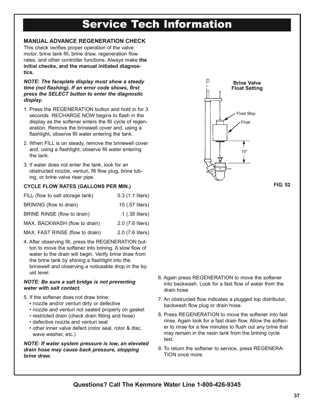
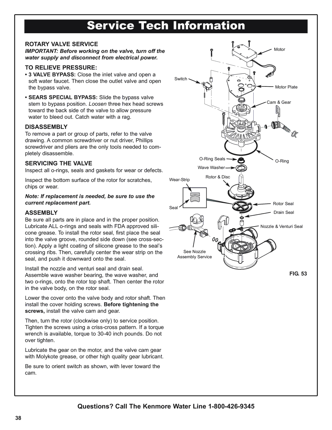
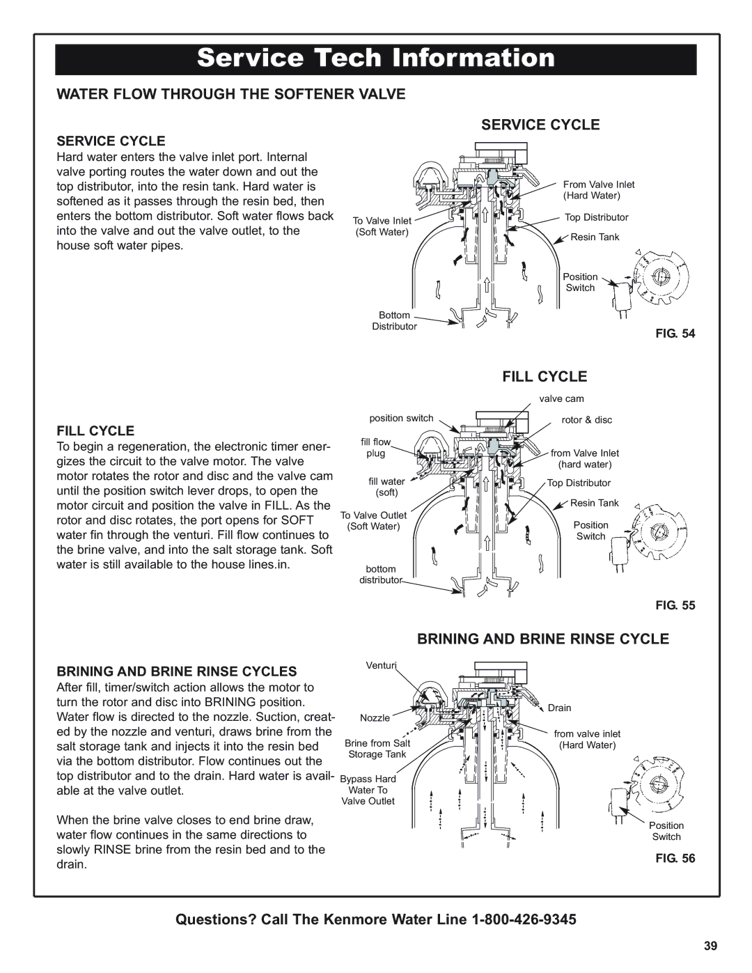
Kenmore 300 Series warranty Troubleshooting Valve Position Indicators, Other Information, Model

Page 36

Service Tech Information

TROUBLESHOOTING

VALVE POSITION INDICATORS:

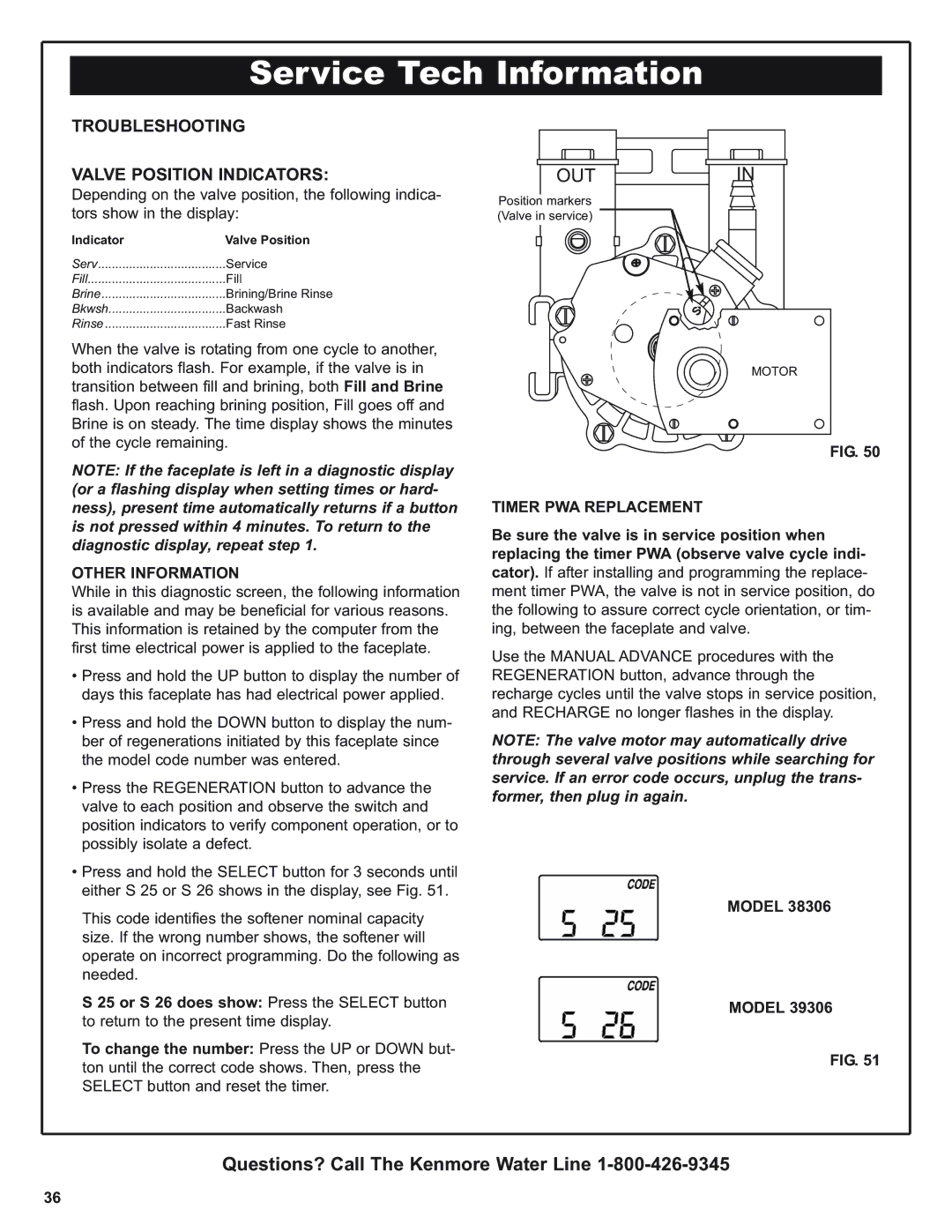
Depending on the valve position, the following indica- tors show in the display:

Indicator

Valve Position

Serv

Service

Fill

Fill

Brine

Brining/Brine Rinse

Bkwsh

Backwash

Rinse

Fast Rinse

When the valve is rotating from one cycle to another, both indicators flash. For example, if the valve is in transition between fill and brining, both Fill and Brine flash. Upon reaching brining position, Fill goes off and Brine is on steady. The time display shows the minutes of the cycle remaining.

NOTE: If the faceplate is left in a diagnostic display (or a flashing display when setting times or hard- ness), present time automatically returns if a button is not pressed within 4 minutes. To return to the diagnostic display, repeat step 1.

OTHER INFORMATION

While in this diagnostic screen, the following information is available and may be beneficial for various reasons. This information is retained by the computer from the first time electrical power is applied to the faceplate.

Press and hold the UP button to display the number of days this faceplate has had electrical power applied.

Press and hold the DOWN button to display the num- ber of regenerations initiated by this faceplate since the model code number was entered.

Press the REGENERATION button to advance the valve to each position and observe the switch and position indicators to verify component operation, or to possibly isolate a defect.

Press and hold the SELECT button for 3 seconds until either S 25 or S 26 shows in the display, see Fig. 51.

This code identifies the softener nominal capacity size. If the wrong number shows, the softener will operate on incorrect programming. Do the following as needed.

S 25 or S 26 does show: Press the SELECT button to return to the present time display.

To change the number: Press the UP or DOWN but- ton until the correct code shows. Then, press the SELECT button and reset the timer.

OUTIN

Position markers (Valve in service)

MOTOR

FIG. 50

TIMER PWA REPLACEMENT

Be sure the valve is in service position when replacing the timer PWA (observe valve cycle indi- cator). If after installing and programming the replace- ment timer PWA, the valve is not in service position, do the following to assure correct cycle orientation, or tim- ing, between the faceplate and valve.

Use the MANUAL ADVANCE procedures with the REGENERATION button, advance through the recharge cycles until the valve stops in service position, and RECHARGE no longer flashes in the display.

NOTE: The valve motor may automatically drive through several valve positions while searching for service. If an error code occurs, unplug the trans- former, then plug in again.

MODEL 38306

MODEL 39306

FIG. 51

Questions? Call The Kenmore Water Line 1-800-426-9345

36

Image 36
Contents Repair or Parts ? Call toll free Save this ManualONE Year Limited Warranty on Water Softener TEN Year Limited Warranty Against LeaksDisclaimer of implied warranties limitation of remedies Table of Contents Facts and Figures to KeepSafety Guides Unpack and Check Your Carton Parts DescriptionsSmall Parts Inspect ShipmentPlan Your Installation Proper Order to Install Water Treating EquipmentPlan Your Installation Tools NeededTypical Installation Where to Install the Water SoftenerSuggested Slab Foundation Installation Draw in Your Pipes and FittingsOUT PIPE, FITTINGS, Other Materials NeededRead Before Beginning Installation Before Installing Checks & TestsInstall Plastic Bypass Valve Assemble Inlet Outlet ADAPTORS, or Plastic Bypass ValveBypass Valve Install 3-Valve Bypass Installing Holding ClipsInstalling 3 Valve Bypass and Pipes Valve BypassLocate Water Softener and Connect Pipes Move Softener Into PlaceTypical Soldering Connections Position Softener Into PlaceConnect Valve and Salt Tank Drains Connect the Valve Drain HoseConnect Salt Tank Overflow Tubing Leak Test House Main Water Shutoff ValvesSingle Bypass Leak TestWater Meter Jumper Wire Connecting TransformerElectrical Requirements Cold Water Pipe GroundingInstall Covers and Restart Water Heater Install CoversInstall Covers Restart the Water HeaterProgram The Timer Program the TimerSET Present Time of DAY SET Water Hardness Number SET Regeneration TimeSET Salt Level Sanitize The Water Softener Sanitize the Water SoftenerSanitize Your Water Softener AS Follows Adding Salt To The Storage Tank Adding Salt to the Storage TankWater Softening Salt with Iron Removing Additives Check List of STEP-BY-STEP Guides to Install Check ListFaceplate Timer Features Extra RechargeRecharge NOW Recharge TonightEfficiency Mode Error CodeTo turn this setting on Program MemoryWater Flow Through Softener in Service Soft Water Service and RegenerationHow Your Water Softener Works Water Flow Through Softener in FillWater Flow Through Softener Brining and Brine Rinse Water Flow Through Softener in BackwashWater Flow Through Softener Fast Rinse Automatic BypassElectronics Care Of Your Water Softener Salt BridgeSalt Bridge Keeping the Water Softener Clean Iron from Resin BEDNozzle & Venturi Drain ALL Water from Softener Protect the Water Softener from FreezingProblem Cause Correction Checklist to Help YOU Save MoneySpecifications Model 38306 Timer Code S Model 39306 Timer Code SBypass Valves InchesOther Specifications Service Tech Information Wiring SchematicFaceplate Always Make These Initial Checks FirstProcedure for Removing Error Code from Faceplate Possible Defect CodeTroubleshooting Valve Position Indicators Timer PWA ReplacementOther Information ModelBrine Valve Float Setting Manual Advance Regeneration CheckCycle Flow Rates Gallons PER MIN Rotary Valve Service DisassemblyAssembly To Relieve PressureWater Flow Through the Softener Valve Service Cycle Fill CycleBrining and Brine Rinse Cycle Water Flow Through the Softener Valve Backwash Cycle Fast Rinse CycleBackwash Cycle Fast Rinse CycleQuestions? Call The Kenmore Water Line Exploded View Parts List Water Softener CompletePart Number Part Description Inlet Outlet Grounding Clamps Brine Valve Assembly Seal Key Part Number Part Description Get it fixed, at your home or ours