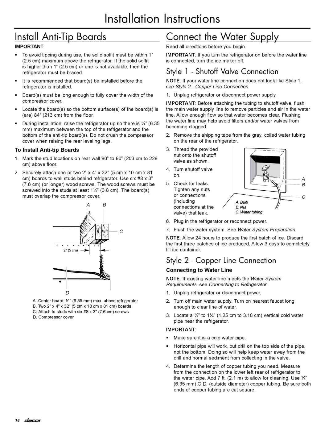
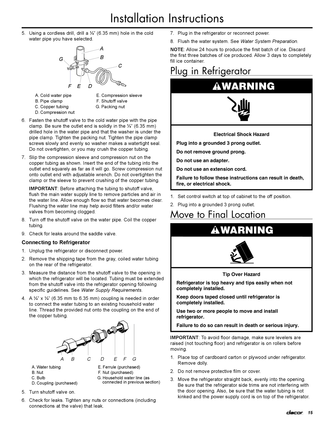
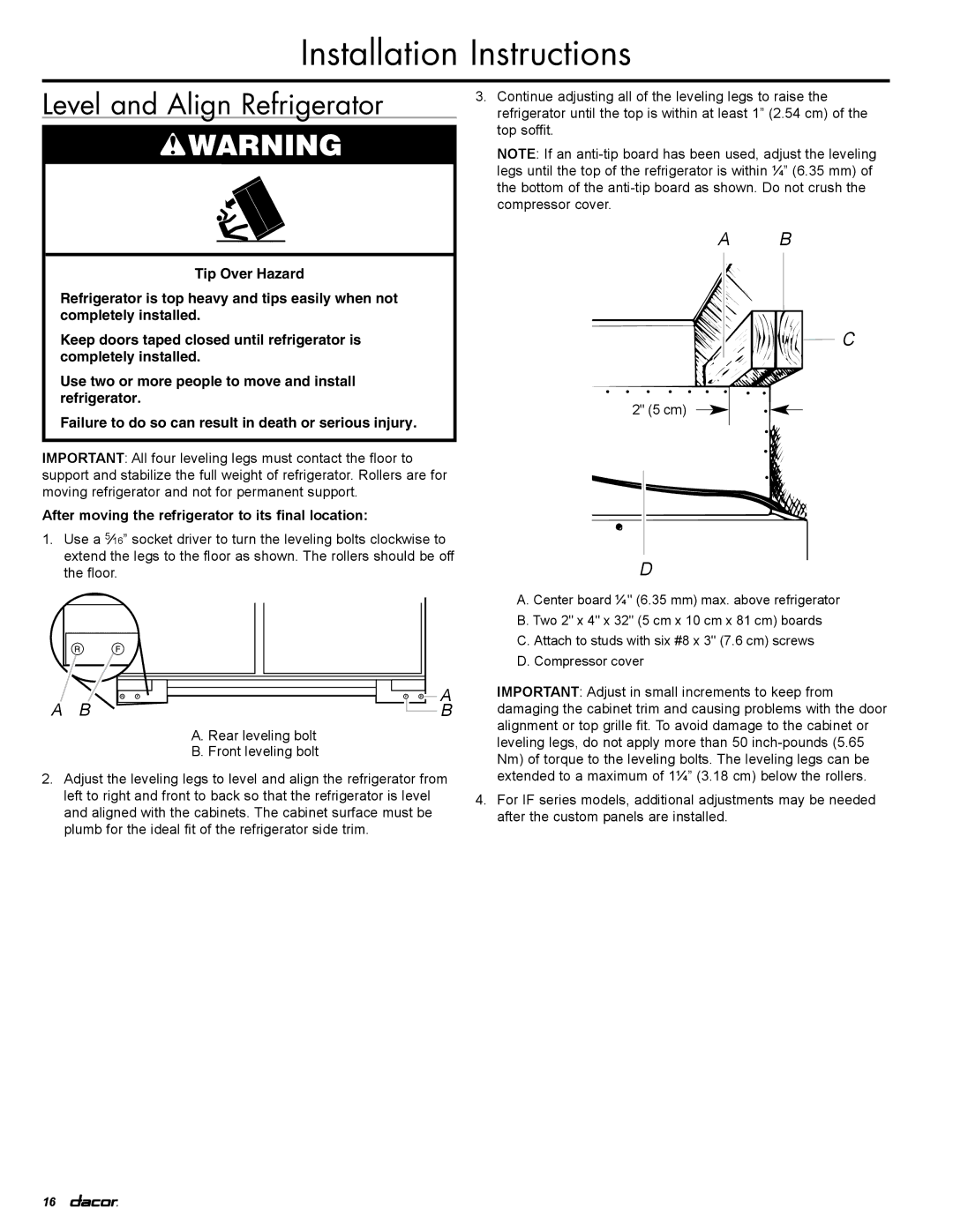
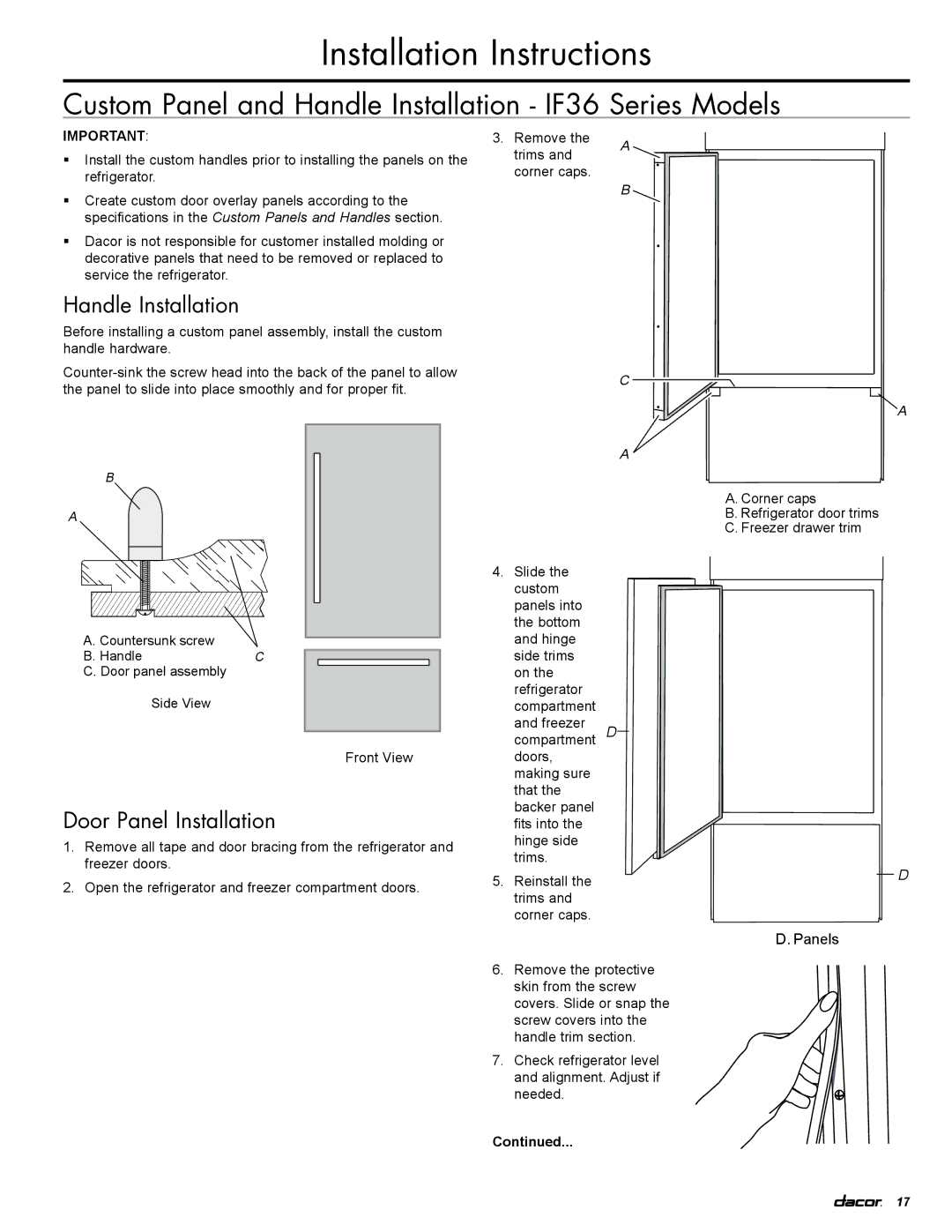
Dacor IF36LNBOL Adjust Doors, Custom Panel Installation IF36 Series Models, Top Grille Panel

Page 20

Installation Instructions

Custom Panel Installation - IF36 Series Models (Continued)

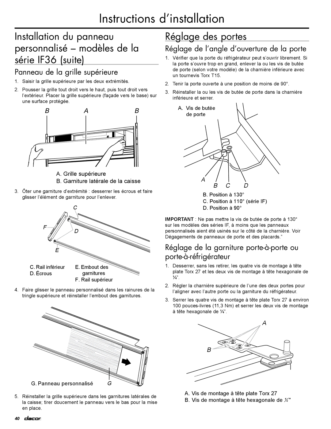
Top Grille Panel

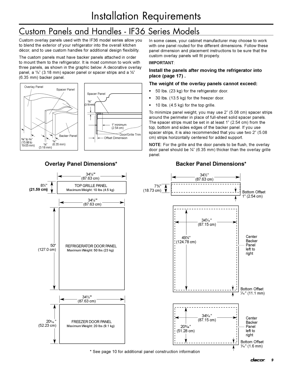
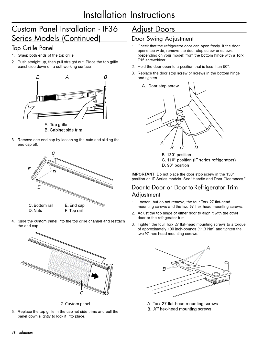
1.Grasp both ends of the top grille.

2.Push straight up, then pull straight out. Place the top grille panel-side down on a soft working surface.

BAB

A. Top grille

B. Cabinet side trim

3.Remove one end cap by loosening the nuts and sliding the end cap off.


C


F

D


E


C. Bottom rail

E. End cap

D. Nuts


F. Top rail

4.Slide the custom panel into the top grille channel and reattach the end cap.

G

G. Custom panel

5. Replace the top grille in the cabinet side trims and pull the panel down slightly to lock it into place.

Adjust Doors

Door Swing Adjustment

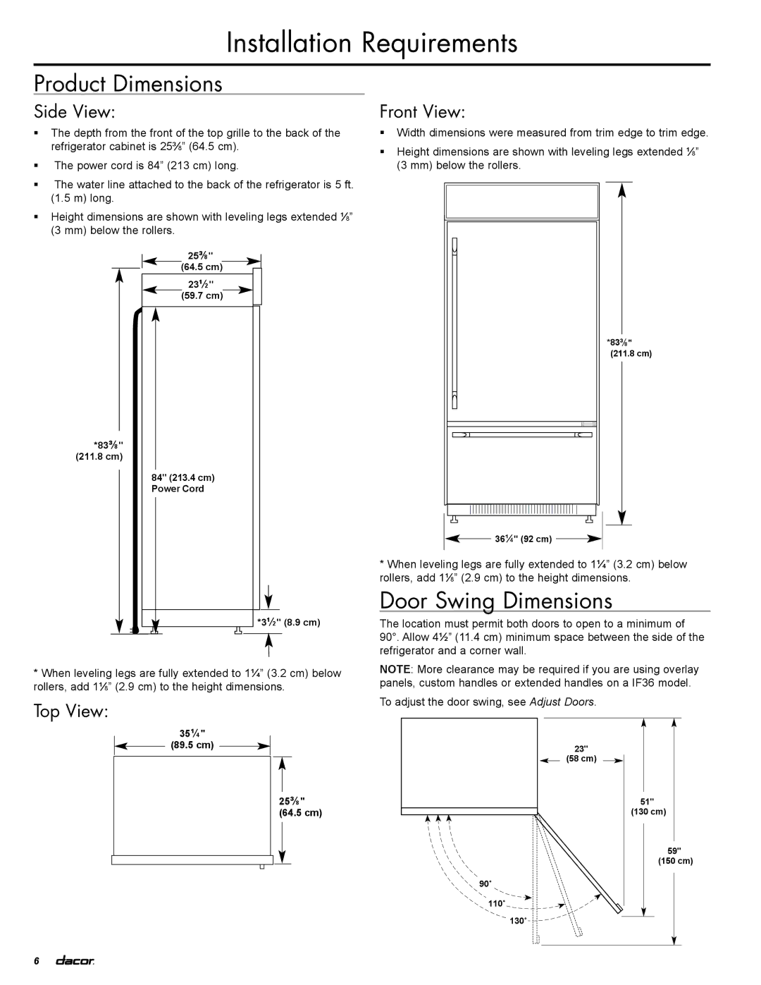
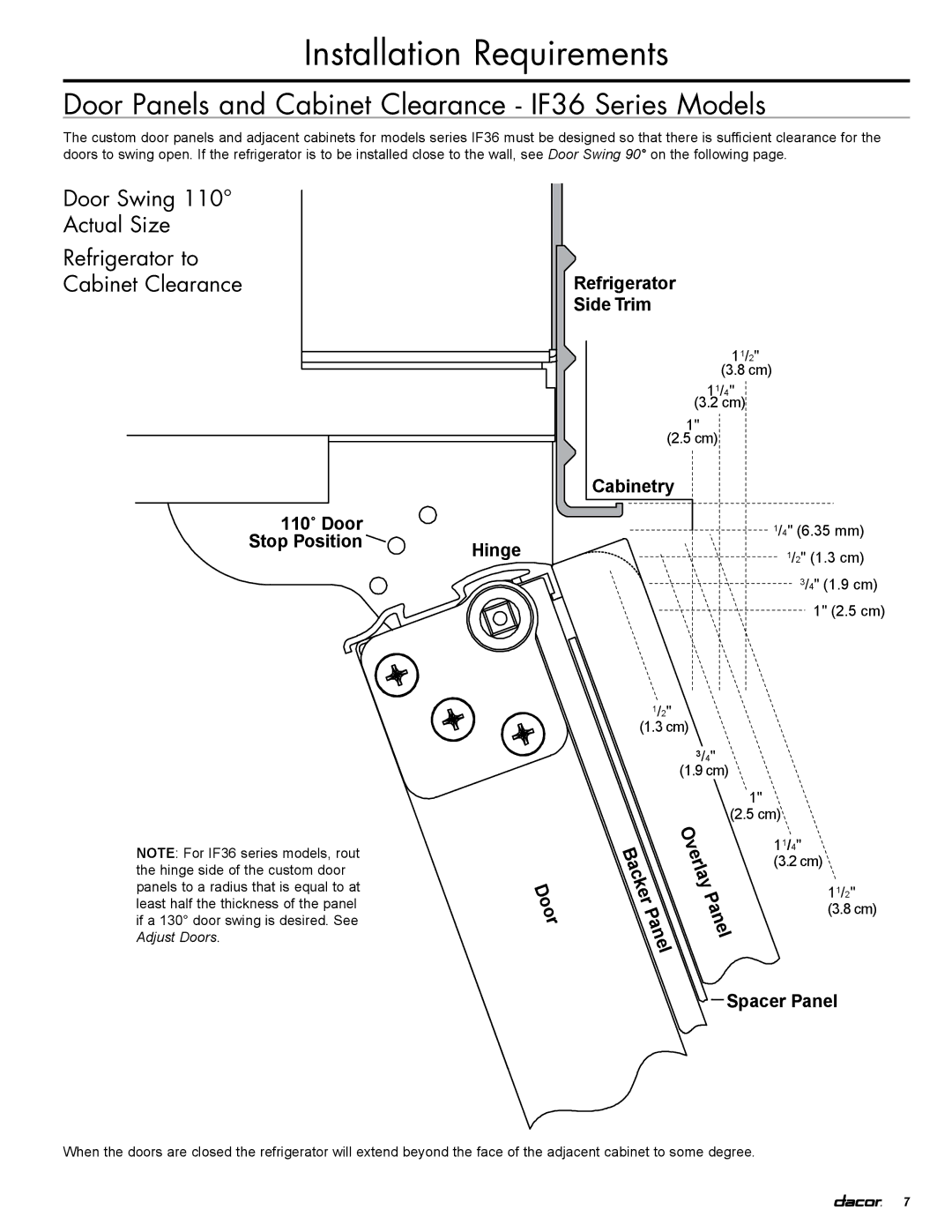
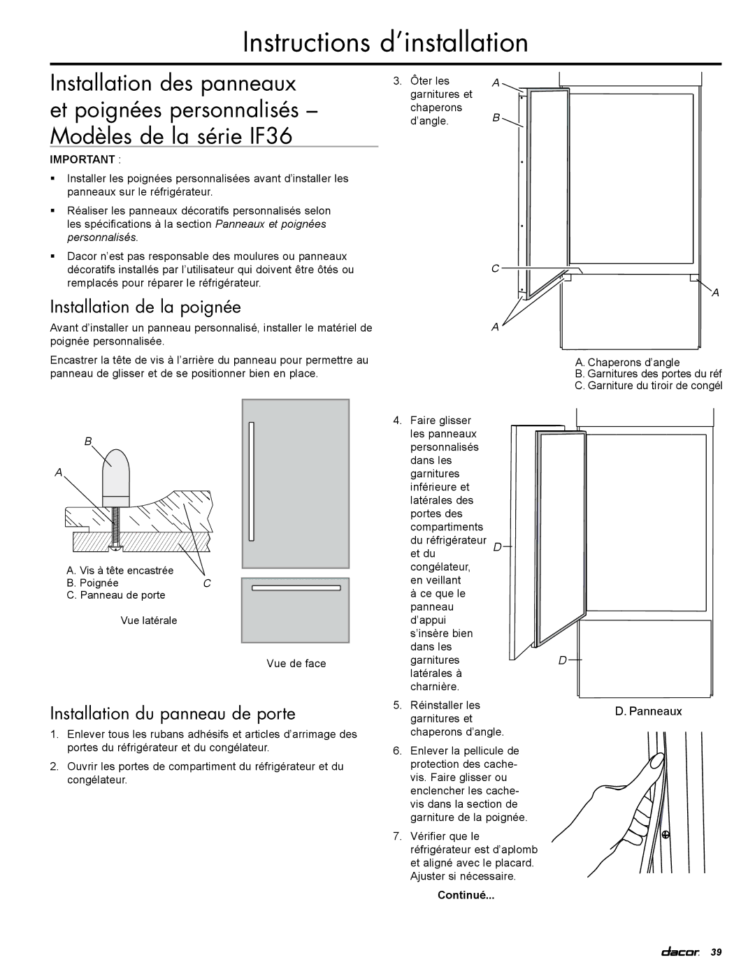
1.Check that the refrigerator door can open freely. If the door opens too wide, remove the door stop screw or screws (depending on your model) from the bottom hinge with a Torx T15 screwdriver.

2.Hold the door open to a position that is less than 90°.

3.Replace the door stop screw or screws in the bottom hinge and tighten.

A.Door stop screw

A

B C D

B. 130° position

C. 110° position (IF series refrigerators)

D. 90° position

IMPORTANT: Do not place the door stop screw in the 130° position on IF Series models. See “Handle and Door Clearances.”

Door-to-Door or Door-to-Refrigerator Trim Adjustment

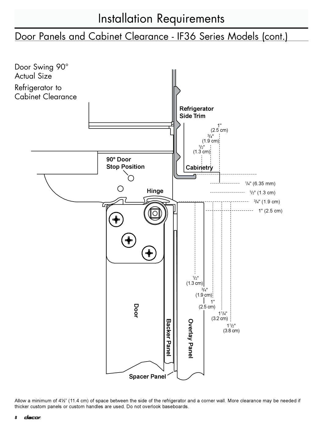
1.Loosen, but do not remove, the four Torx 27 flat-head mounting screws and the two ¼” hex head mounting screws.

2.Adjust the top hinge of either door to align it with the other door or the refrigerator trim.

3.Tighten the four Torx 27 flat-head mounting screws to a torque of approximately 100 inch-pounds (11.3 Nm) and tighten the two ¼” hex head mounting screws.

A

B

A.Torx 27 flat-head mounting screws

B.¹⁄4 " hex-head mounting screws

18

Image 20
Contents Installation Instructions Inch Built-In Refrigerator Table of Contents Customer Service InformationRefrigerator Safety Model Identification EF36LNBSSInstallation Requirements Opening DimensionsTools and Parts Location RequirementsRecommended Grounding Method Electrical RequirementsLocation Requirements Water Supply Requirements Tipping RadiusWater Pressure Side Tipping RadiusProduct Dimensions Door Swing DimensionsSide View Top ViewDoor Panels and Cabinet Clearance IF36 Series Models Door Swing Actual Size Refrigerator to Cabinet ClearanceDoor Swing 90 Actual Size Refrigerator to Cabinet Clearance AnelCustom Panels and Handles IF36 Series Models Install the panels after moving the refrigerator into placeWeight of the overlay panels cannot exceed Piece Grille Overlay Panel Configuration Piece Door Overlay Panel ConfigurationPiece Overlay Panel Configuration Custom Panels Construction InformationRefrigerator and Side Trim Dimensions Inset Installation DimensionsRecessed Inset Installation Dimensions Custom Side Panels Model IF36Flush Installation Dimensions Custom Side Panels Model EF36Back Wall Refrigerator BackInstallation Instructions Unpack the RefrigeratorReduce Tipping Radius Move Refrigerator into HouseInstall Anti-Tip Boards Connect the Water SupplyStyle 1 Shutoff Valve Connection Style 2 Copper Line ConnectionMove to Final Location Connecting to RefrigeratorPlug in Refrigerator Level and Align Refrigerator After moving the refrigerator to its final locationDoor Panel Installation Custom Panel and Handle Installation IF36 Series ModelsHandle Installation Adjust Doors Custom Panel Installation IF36 Series ModelsDoor Swing Adjustment Door-to-Door or Door-to-Refrigerator Trim AdjustmentInstall Side Panels Install Base GrilleComplete Installation Water System PreparationInstructions d’installation Réfrigérateur Encastré de Information pour le service à la clientèle Exigences d’installationSécurité du réfrigérateur Identification des modèles Exigences d’installation Exigences d’emplacementDimensions de l’ouverture Outillage et composantsSpécifications électriques Exigences d’emplacement suiteMéthode recommandée de liaison à la terre Rayon de basculement Exigences de l’alimentation en eauPression de l’eau Rayon de basculement latéralDimensions du produit Dimensions pour le pivotement des portesVue latérale Vue avantDégagement Réfrigérateur/placard Position de butée 110˚Pivotement à 90 Dimensions réelles Panneau décoratifs Dimensions Panneau d’appui Dimensions Panneaux et poignées personnalisés modèle de la série IF36Information sur la construction des panneaux personnalisés Poignées personnalisésDimensions du réfrigérateur et des garnitures latérales Dimensions pour une installation en encastrementDimensions pour une installation en encastrement en retrait Panneaux latéraux personnalisés modèle IF36Dimensions pour une installation en affleurement Instructions d’installation Déballage du réfrigérateurFaire entrer le réfrigérateur dans le domicile Réduction du rayon de basculement si nécessaireRaccordement à la canalisation d’eau Installation de planches antibasculementInstallation de planches antibasculement Brancher le réfrigérateur Raccordement au réfrigérateurRéglage de l’aplomb et alignement du réfrigérateur Installation de la poignée Installation du panneau de porteRéglage de l’angle d’ouverture de la porte Réglage des portesPanneau de la grille supérieure Installation des panneaux latéraux Installation de la grille de la baseAchever l’installation Préparation du système d’eauPage Page