Installing and Removing a Power Supply
Power Supply Planning
Although each power supply requires its own circuit, when planning the X4‐C power budget you have the option of drawing from one or more sources by either the N + 1 or 1 + 1 method, respectively.
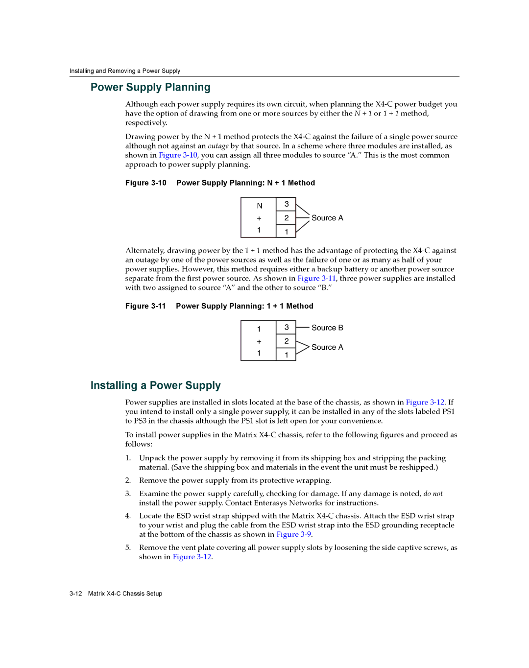
Drawing power by the N + 1 method protects the X4‐C against the failure of a single power source although not against an outage by that source. In a scheme where three modules are installed, as shown in Figure 3‐10, you can assign all three modules to source “A.” This is the most common approach to power supply planning.
Figure 3-10 Power Supply Planning: N + 1 Method
N
+
1
3
2
1
Source A
Alternately, drawing power by the 1 + 1 method has the advantage of protecting the X4‐C against an outage by one of the power sources as well as the failure of one or as many as half of your power supplies. However, this method requires either a backup battery or another power source separate from the first power source. As shown in Figure 3‐11, three power supplies are installed with two assigned to source “A” and the other to source “B.”
Figure 3-11 Power Supply Planning: 1 + 1 Method
13 Source B
+ | 2 | Source A | |
1 | 1 | ||
|
Installing a Power Supply
Power supplies are installed in slots located at the base of the chassis, as shown in Figure 3‐12. If you intend to install only a single power supply, it can be installed in any of the slots labeled PS1 to PS3 in the chassis although the PS1 slot is left open for your convenience.
To install power supplies in the Matrix X4‐C chassis, refer to the following figures and proceed as follows:
1.Unpack the power supply by removing it from its shipping box and stripping the packing material. (Save the shipping box and materials in the event the unit must be reshipped.)
2.Remove the power supply from its protective wrapping.
3.Examine the power supply carefully, checking for damage. If any damage is noted, do not install the power supply. Contact Enterasys Networks for instructions.
4.Locate the ESD wrist strap shipped with the Matrix X4‐C chassis. Attach the ESD wrist strap to your wrist and plug the cable from the ESD wrist strap into the ESD grounding receptacle at the bottom of the chassis as shown in Figure 3‐9.
5.Remove the vent plate covering all power supply slots by loosening the side captive screws, as shown in Figure 3‐12.