Powering Up the Matrix
6.Reattach the bar to the cable management assembly by tightening the two (2) captive screws on the bar.
7.If you wish to remove a cable strap, simply unscrew it from the cable management base panel.
Powering Up the Matrix X4-C Chassis
To power up the Matrix X4‐C chassis, proceed as follows:
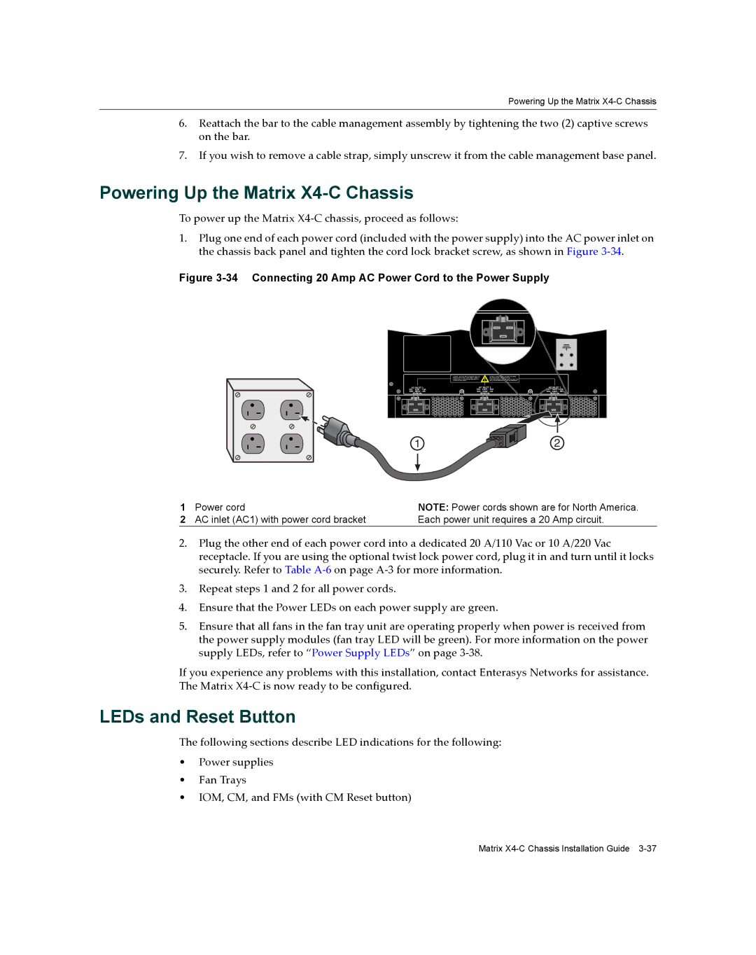
1.Plug one end of each power cord (included with the power supply) into the AC power inlet on the chassis back panel and tighten the cord lock bracket screw, as shown in Figure 3‐34.
Figure 3-34 Connecting 20 Amp AC Power Cord to the Power Supply
| AC INLET 3 | AC INLET 2 |
| AC INLET 1 | ||||||||
| 100 - 125V ~ 15A | 100 - 125V ~ 15A |
| 100 - 125V ~ 15A | ||||||||
| 200 - 240V ~ 8A | 200 - 240V ~ 8A |
| 200 - 240V ~ 8A | ||||||||
|
| 50/60 Hz | 50/60 Hz |
| 50/60 Hz | |||||||
|
|
|
|
|
|
|
|
|
|
|
|
|
|
|
|
|
|
|
|
|
|
|
|
|
|
|
|
|
|
|
|
|
|
|
|
|
|
|
1
2
1 | Power cord | NOTE: Power cords shown are for North America. |
2 | AC inlet (AC1) with power cord bracket | Each power unit requires a 20 Amp circuit. |
2.Plug the other end of each power cord into a dedicated 20 A/110 Vac or 10 A/220 Vac receptacle. If you are using the optional twist lock power cord, plug it in and turn until it locks securely. Refer to Table A‐6 on page A‐3 for more information.
3.Repeat steps 1 and 2 for all power cords.
4.Ensure that the Power LEDs on each power supply are green.
5.Ensure that all fans in the fan tray unit are operating properly when power is received from the power supply modules (fan tray LED will be green). For more information on the power supply LEDs, refer to “Power Supply LEDs” on page 3‐38.
If you experience any problems with this installation, contact Enterasys Networks for assistance. The Matrix X4‐C is now ready to be configured.
LEDs and Reset Button
The following sections describe LED indications for the following:
•Power supplies
•Fan Trays
•IOM, CM, and FMs (with CM Reset button)
Matrix