|
|
| LEDs and Reset Button | |
|
|
| ||
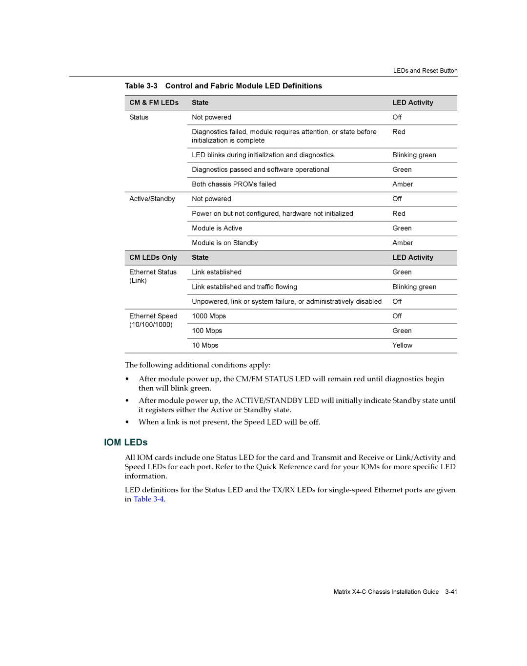
| Table |
| ||
|
|
|
| |
| CM & FM LEDs | State | LED Activity | |
|
|
|
| |
| Status | Not powered | Off | |
|
|
|
| |
|
| Diagnostics failed, module requires attention, or state before | Red | |
|
| initialization is complete |
| |
|
|
|
| |
|
| LED blinks during initialization and diagnostics | Blinking green | |
|
|
|
| |
|
| Diagnostics passed and software operational | Green | |
|
|
|
| |
|
| Both chassis PROMs failed | Amber | |
|
|
|
| |
| Active/Standby | Not powered | Off | |
|
|
|
| |
|
| Power on but not configured, hardware not initialized | Red | |
|
|
|
| |
|
| Module is Active | Green | |
|
|
|
| |
|
| Module is on Standby | Amber | |
|
|
|
| |
| CM LEDs Only | State | LED Activity | |
|
|
|
| |
| Ethernet Status | Link established | Green | |
| (Link) |
|
| |
| Link established and traffic flowing | Blinking green | ||
|
| |||
|
|
|
| |
|
| Unpowered, link or system failure, or administratively disabled | Off | |
|
|
|
| |
| Ethernet Speed | 1000 Mbps | Off | |
(10/100/1000) |
|
| ||
100 Mbps | Green | |||
|
| |||
|
|
|
| |
|
| 10 Mbps | Yellow | |
|
|
|
| |
The following additional conditions apply:
•After module power up, the CM/FM STATUS LED will remain red until diagnostics begin then will blink green.
•After module power up, the ACTIVE/STANDBY LED will initially indicate Standby state until it registers either the Active or Standby state.
•When a link is not present, the Speed LED will be off.
IOM LEDs
All IOM cards include one Status LED for the card and Transmit and Receive or Link/Activity and Speed LEDs for each port. Refer to the Quick Reference card for your IOMs for more specific LED information.
LED definitions for the Status LED and the TX/RX LEDs for single‐speed Ethernet ports are given in Table 3‐4.
Matrix