|
|
|
|
|
|
|
|
| Installing and Removing Modules | ||
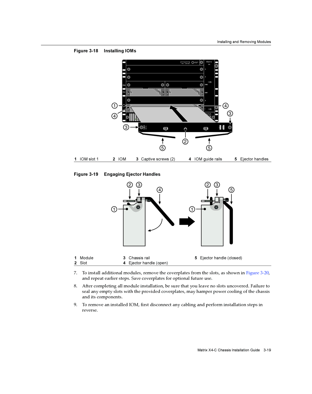
Figure |
|
|
|
|
|
|
|
| |||
|
|
|
|
|
|
| GROUND | Matrix |
|
|
|
|
|
|
|
|
| S/N: MAC ADD. | STRAP |
|
|
|
|
|
|
|
|
|
|
|
| X4 |
|
|
|
|
|
|
|
|
|
| 4 |
|
|
|
|
|
|
|
|
|
|
| 3 |
|
|
|
|
|
|
|
|
|
|
|
| FAN |
|
|
|
|
|
|
|
|
|
|
| TRAY |
|
|
|
|
| FM2 |
|
|
|
| CM2 |
|
|
| |
|
|
|
|
|
|
|
|
|
|
| |
|
| FM1 |
|
|
|
| CM1 |
|
|
| |
|
|
|
|
|
|
| 2 |
|
|
|
|
| 1 |
|
|
|
|
| 1 | FAN |
| 4 |
|
|
|
|
|
|
|
|
|
|
| ||
|
|
|
|
|
|
|
| TRAY |
|
|
|
| 4 |
|
|
|
|
|
|
|
| 3 |
|
|
|
|
|
|
|
|
|
|
|
| |
|
| 3 |
| TX RX |
| TX | RX | S/N: | MAC ADD. |
| |
|
|
|
|
| TX RX |
| TX | RX |
|
|
|
|
|
|
|
|
| 2 |
|
|
|
|
|
|
|
|
|
| 5 |
|
| 5 |
|
|
|
1 IOM slot 1 | 2 | IOM | 3 | Captive screws (2) | 4 | IOM guide rails | 5 | Ejector handles | |||
Figure |
|
| |
2 | 3 | 2 | 3 |
| 4 |
| 5 |
1 |
| 1 |
|
1 | Module | 3 | Chassis rail | 5 Ejector handle (closed) |
2 | Slot | 4 | Ejector handle (open) |
|
7.To install additional modules, remove the coverplates from the slots, as shown in Figure 3‐20, and repeat earlier steps. Save coverplates for optional future use.
8.After completing all module installation, be sure that you leave no slots uncovered. Failure to seal any empty slots with the provided coverplates, may hamper power cooling of the chassis and its components.
9.To remove an installed IOM, first disconnect any cabling and perform installation steps in reverse.
Matrix