Installing and Removing a Power Supply
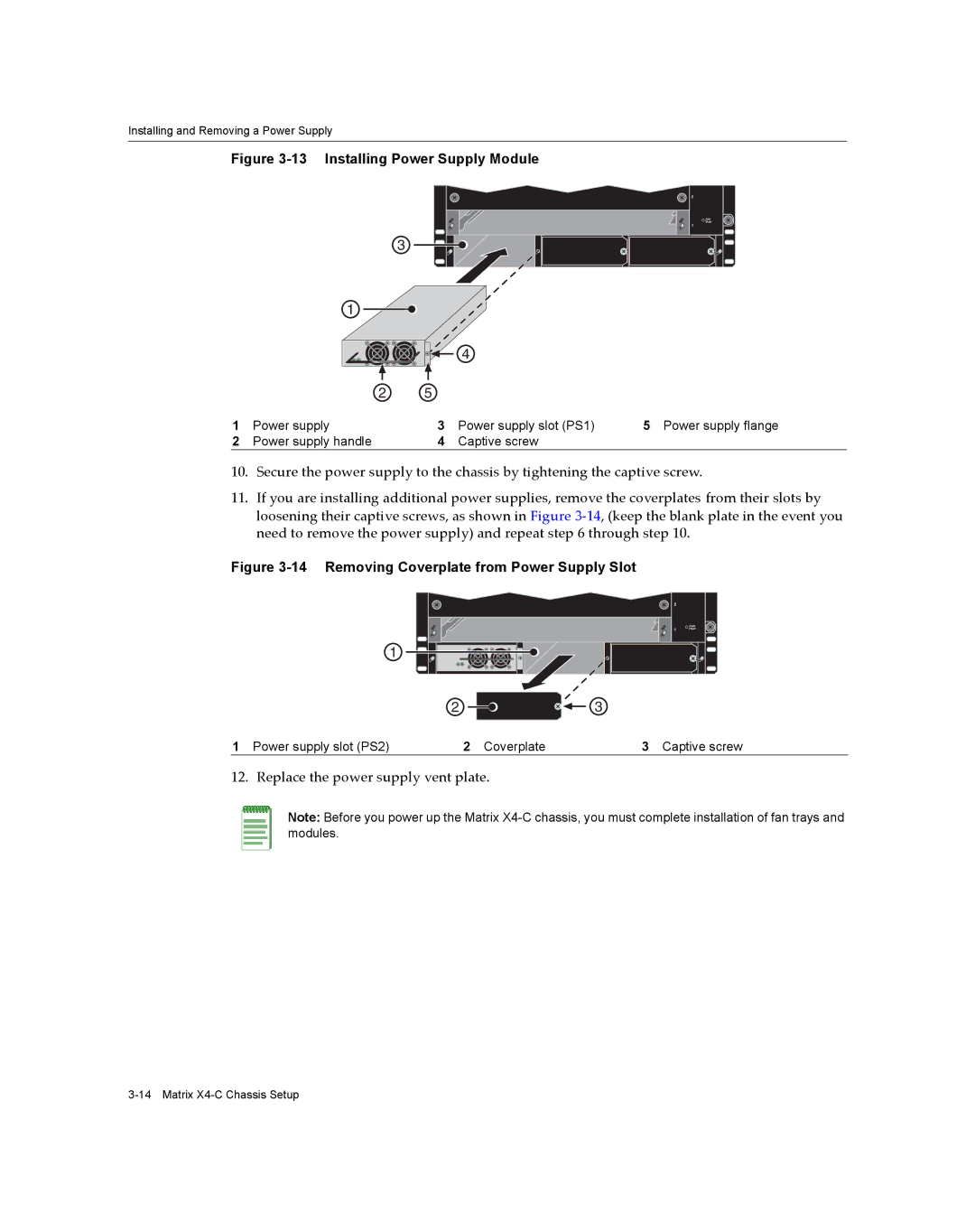
Figure 3-13 Installing Power Supply Module
3
2
FAN |
TRAY |
1 |
| 1 |
|
|
|
|
|
| 4 |
|
| 2 | 5 |
|
|
1 | Power supply | 3 | Power supply slot (PS1) | 5 Power supply flange |
2 | Power supply handle | 4 | Captive screw |
|
10.Secure the power supply to the chassis by tightening the captive screw.
11.If you are installing additional power supplies, remove the coverplates from their slots by loosening their captive screws, as shown in Figure 3‐14, (keep the blank plate in the event you need to remove the power supply) and repeat step 6 through step 10.
Figure 3-14 Removing Coverplate from Power Supply Slot
2 |
|
| X4 |
2 |
|
1 | FAN |
TRAY | |
1 |
|
2 ![]()
![]()
![]() 3
3
1 Power supply slot (PS2) | 2 Coverplate | 3 Captive screw |
12. Replace the power supply vent plate.
Note: Before you power up the Matrix