Installing and Removing a Fan Tray
Installing and Removing a Fan Tray
The Matrix X4‐C chassis is equipped with removable fan trays that allow for easy periodic replacement if a fan fails. To install and remove a fan tray, refer to “Installing a Fan Tray” on page 3‐16 and “Removing a Fan Tray” on page 3‐17.
Caution: A fan tray is
Precaución: El sistema de ventilación se puede reemplazar cuando la unidad está encendida. Sin embargo, no utilice el chasis durante largos períodos sin contar con un sistema de ventilación porque podría sobrecalentarse y dañarse.
Installing a Fan Tray
To install a fan tray, refer to the figures below as indicated in the steps below and proceed as follows:
1.Locate the ESD wrist strap shipped with the Matrix X4‐C chassis. Attach the ESD wrist strap to your wrist and plug the cable from the ESD wrist strap into the ESD grounding receptacle at the bottom of the chassis as shown in Figure 3‐9.
2.Unpack the fan tray by taking it from its shipping box and removing any packaging materials. (Save the shipping box and materials in the event the unit must be reshipped.)
3.Remove the fan tray from its protective plastic bag.
4.Examine the fan tray carefully, checking for damage. If any damage is noted, do not install it. Contact Enterasys Networks for instructions.
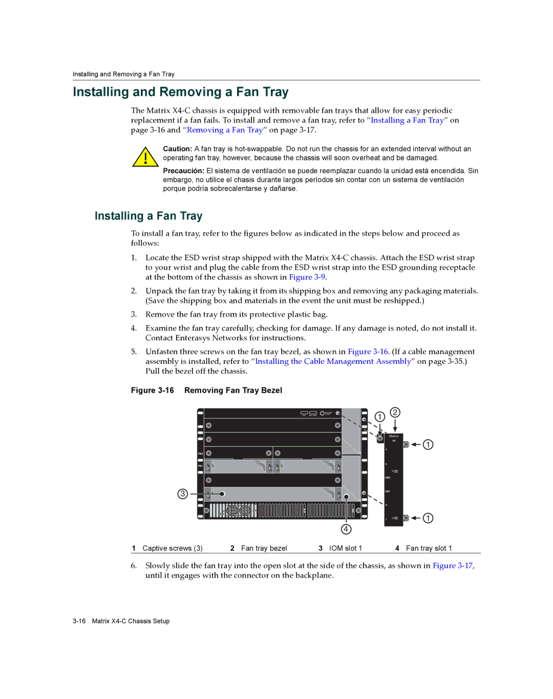
5.Unfasten three screws on the fan tray bezel, as shown in Figure 3‐16. (If a cable management assembly is installed, refer to “Installing the Cable Management Assembly” on page 3‐35.) Pull the bezel off the chassis.
Figure 3-16 Removing Fan Tray Bezel
FM2
FM1
3
S/N: MAC ADD.
GROUND
STRAP
4 |
1 | 2 |
|
|
| |
Matrix | ||
| X4 |
|
4 |
|
|
4 |
|
|
3 |
|
|
3 | FAN | FAN |
TRAYTRAY | ||
CM2 |
| 2 |
CM2 |
|
|
|
| FAN |
|
| TRAY |
CM1 |
| 1 |
CM1 |
|
|
2 |
|
|
2 | X4 | |
|
| |
1 | FAN |
|
TRAY |
| |
1 |
|
|
1
1
1Captive screws (3)
2 Fan tray bezel | 3 IOM slot 1 |
4 |
Fan tray slot 1
6.Slowly slide the fan tray into the open slot at the side of the chassis, as shown in Figure 3‐17, until it engages with the connector on the backplane.