Attaching Cables, Installing Compact Flash Card and DIMM Upgrade Kit
The procedure below describes how to connect an LC or MT‐RJ cable connector to an XFP or SFP port connector, respectively.
1.Remove the protective covers (not shown) from the LC or MT‐RJ fiber‐optic port on the transceiver and from the connectors on each end of the cable.
Note: Leave the protective covers in place when the connectors are not in use to prevent contamination.
Caution: Do not touch the ends of the
Precaución: No toque los extremos de los cables de fibra óptica y evite su contacto con el polvo, la suciedad o con cualquier otro contaminante. Si los extremos de los cables se ensucian, es posible que la transmisión de datos se vea afectada. Si nota que los extremos de los cables de fibra óptica se ensucian, utilice aire comprimido para limpiarlos. También puede limpiarlos con un estropajo embebido en alcohol isopropílico.
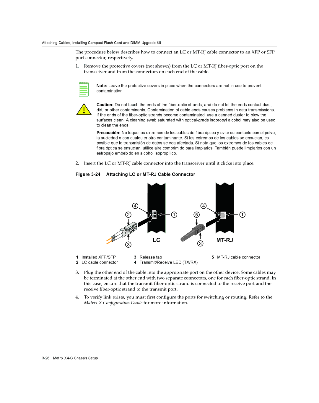
2.Insert the LC or MT‐RJ cable connector into the transceiver until it clicks into place.
Figure 3-24 Attaching LC or MT-RJ Cable Connector
4 | 4 |
2 | TX | TXRX | 1 | 5 | TX |
1
|
| 3 | LC | 3 |
|
|
|
|
| ||
1 | Installed XFP/SFP | 3 | Release tab |
| 5 |
2 | LC cable connector | 4 | Transmit/Receive LED (TX/RX) |
|
|
3.Plug the other end of the cable into the appropriate port on the other device. Some cables may be terminated at the other end with two separate connectors, one for each fiber‐optic strand. In this case, ensure that the transmit fiber‐optic strand is connected to the receive port and the receive fiber‐optic strand to the transmit port.
4.To verify link exists, you must first configure the ports for switching or routing. Refer to the Matrix X Configuration Guide for more information.