Attaching Cables, Installing Compact Flash Card and DIMM Upgrade Kit
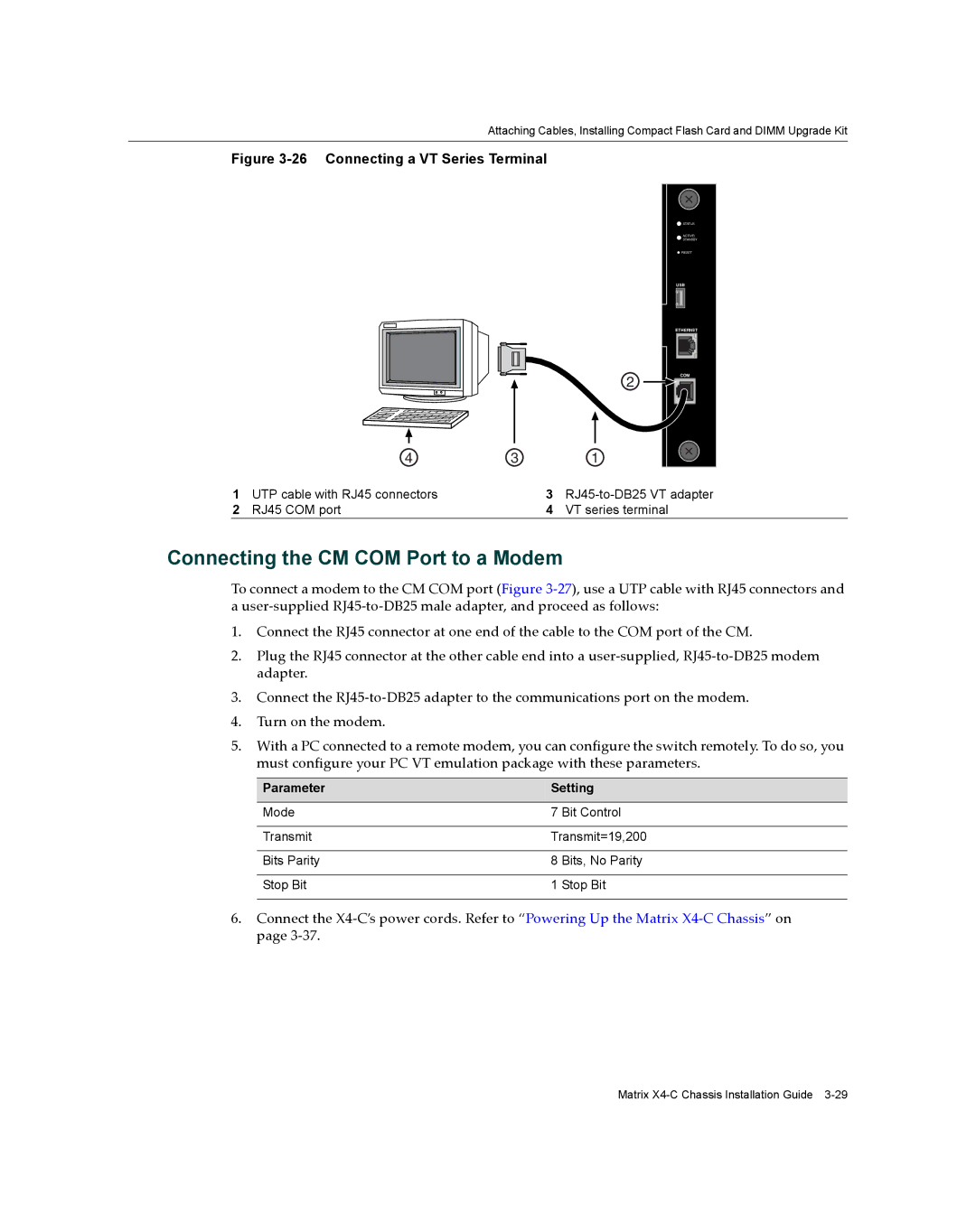
Figure 3-26 Connecting a VT Series Terminal
2
4 | 3 | 1 |
STATUS
ACTIVE/
STANDBY
RESET
USB
ETHERNET |
COM
1 | UTP cable with RJ45 connectors | 3 | |
2 | RJ45 COM port | 4 | VT series terminal |
Connecting the CM COM Port to a Modem
To connect a modem to the CM COM port (Figure 3‐27), use a UTP cable with RJ45 connectors and
auser‐supplied RJ45‐to‐DB25 male adapter, and proceed as follows:
1.Connect the RJ45 connector at one end of the cable to the COM port of the CM.
2.Plug the RJ45 connector at the other cable end into a user‐supplied, RJ45‐to‐DB25 modem adapter.
3.Connect the RJ45‐to‐DB25 adapter to the communications port on the modem.
4.Turn on the modem.
5.With a PC connected to a remote modem, you can configure the switch remotely. To do so, you must configure your PC VT emulation package with these parameters.
Parameter | Setting | |
|
| |
Mode | 7 Bit Control | |
|
| |
Transmit | Transmit=19,200 | |
|
|
|
Bits Parity | 8 | Bits, No Parity |
|
|
|
Stop Bit | 1 | Stop Bit |
|
|
|
6.Connect the X4‐C’s power cords. Refer to “Powering Up the Matrix X4‐C Chassis” on page 3‐37.
Matrix