Setting Up the Matrix
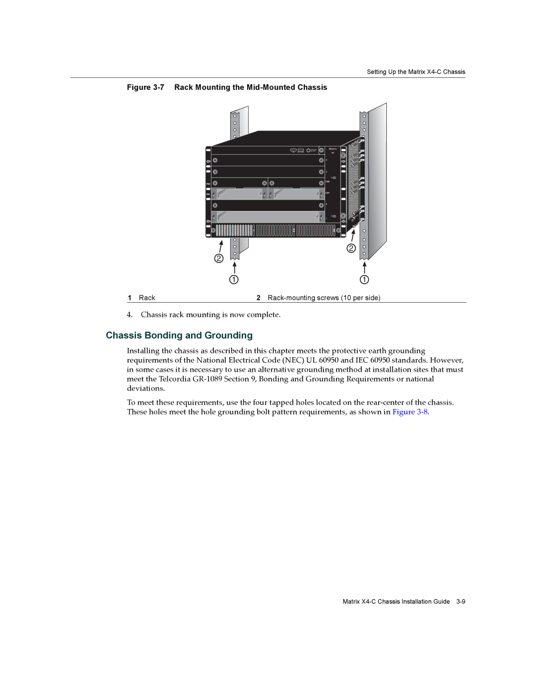
Figure 3-7 Rack Mounting the Mid-Mounted Chassis
| GROUND | Matrix |
S/N: | STRAP |
|
MAC ADD. | X4 | |
|
| |
|
| 4 |
|
| 3 |
|
| FAN |
|
| TRAY |
|
| CM2 |
FM2 |
|
|
FM1 |
| CM1 |
|
| |
|
| 2 |
|
| FAN |
|
| TRAY |
|
| 1 |
|
| 2 |
2 |
|
|
1 |
| 1 |
1 Rack | 2 |
4.Chassis rack mounting is now complete.
Chassis Bonding and Grounding
Installing the chassis as described in this chapter meets the protective earth grounding requirements of the National Electrical Code (NEC) UL 60950 and IEC 60950 standards. However, in some cases it is necessary to use an alternative grounding method at installation sites that must meet the Telcordia GR‐1089 Section 9, Bonding and Grounding Requirements or national deviations.
To meet these requirements, use the four tapped holes located on the rear‐center of the chassis. These holes meet the hole grounding bolt pattern requirements, as shown in Figure 3‐8.
Matrix