Optional Cable Management Kit
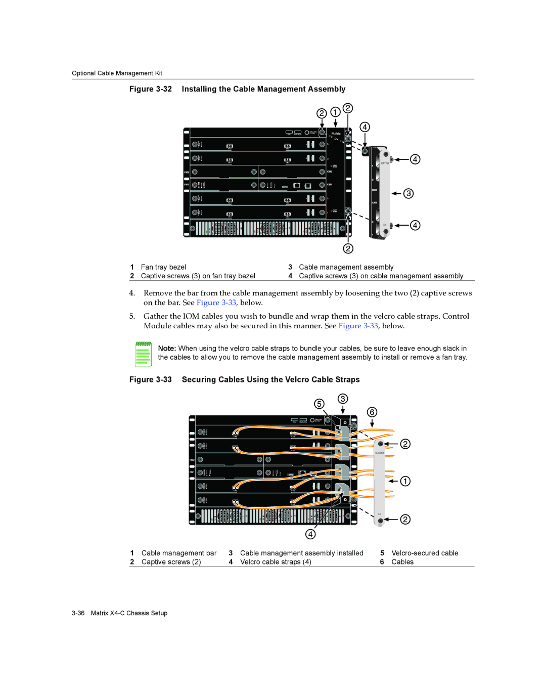
Figure 3-32 Installing the Cable Management Assembly
1 | Fan tray bezel | 3 | Cable management assembly |
2 | Captive screws (3) on fan tray bezel | 4 | Captive screws (3) on cable management assembly |
4.Remove the bar from the cable management assembly by loosening the two (2) captive screws on the bar. See Figure 3‐33, below.
5.Gather the IOM cables you wish to bundle and wrap them in the velcro cable straps. Control Module cables may also be secured in this manner. See Figure 3‐33, below.
Note: When using the velcro cable straps to bundle your cables, be sure to leave enough slack in the cables to allow you to remove the cable management assembly to install or remove a fan tray.
Figure 3-33 Securing Cables Using the Velcro Cable Straps
1 | Cable management bar | 3 | Cable management assembly installed | 5 | |
2 | Captive screws (2) | 4 | Velcro cable straps (4) | 6 | Cables |