LEDs and Reset Button
The following additional conditions apply:
•After power up, the fan tray LED remains red until diagnostics begin, then will blink green. When blinking amber, the fan controller will run a default configuration.
•An overheating warning indicates fans are running at high speed. Fans operate at normal speed if no warning is received.
Caution: If the LED remains red, replace the fan tray immediately. Otherwise, the system may overheat and damage chassis components.
Precaución: Si observa que la lucecita roja no se apaga, cambie inmediatamente el sistema de ventilación. Si no lo hace, el sistema se sobrecalentará y los componentes del chasis se dañarán.
Module LEDs and Reset Button
Control and Fabric Module LEDs
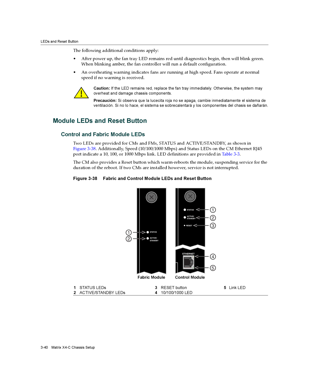
Two LEDs are provided for CMs and FMs, STATUS and ACTIVE/STANDBY, as shown in Figure 3‐38. Additionally, Speed (10/100/1000 Mbps) and Status LEDs on the CM Ethernet RJ45 port indicate a 10, 100, or 1000 Mbps link. LED definitions are provided in Table 3‐3.
The CM also provides a Reset button which warm‐reboots the module, suspending service for the duration of the reboot. If two CMs are installed however, service is not interrupted.
Figure 3-38 Fabric and Control Module LEDs and Reset Button
![]() STATUS
STATUS
ACTIVE/
STANDBY
![]() RESET
RESET ![]()
1
2
3
1
2
![]()
![]() STATUS
STATUS
![]() ACTIVE/
ACTIVE/
STANDBY
1STATUS LEDs
2ACTIVE/STANDBY LEDs
ETHERNET |
Fabric Module | Control Module |
3RESET button
410/100/1000 LED
4
5
5Link LED