Installing and Removing Modules
Installing and Removing FMs
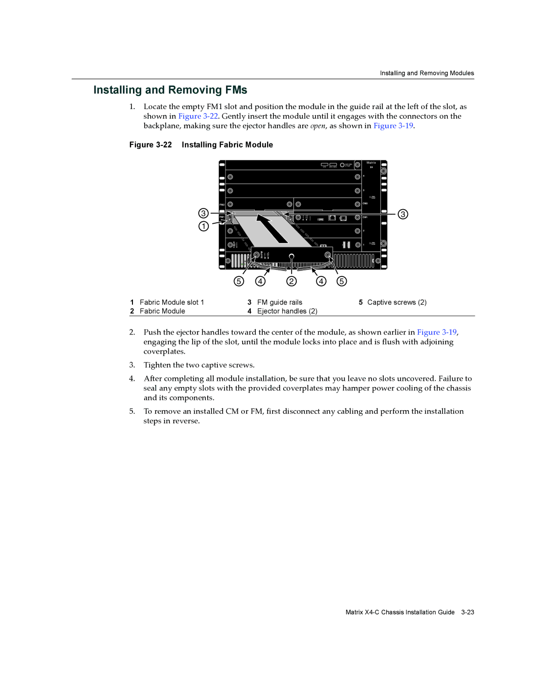
1.Locate the empty FM1 slot and position the module in the guide rail at the left of the slot, as shown in Figure 3‐22. Gently insert the module until it engages with the connectors on the backplane, making sure the ejector handles are open, as shown in Figure 3‐19.
Figure 3-22 Installing Fabric Module
|
|
|
|
|
|
|
|
|
|
| Matrix |
| ||
|
|
|
|
|
|
|
|
|
|
| GROUND |
|
|
|
|
|
|
|
|
|
|
| S/N: | MAC ADD. | STRAP | X4 |
|
| |
|
|
|
|
|
|
|
|
|
|
| ||||
|
|
|
|
|
|
|
|
|
|
| 4 |
|
|
|
|
|
|
|
|
|
|
|
|
|
| 4 |
|
|
|
|
|
|
|
|
|
|
|
|
|
| 3 |
|
|
|
|
|
|
|
|
|
|
|
|
|
| 3 | FAN | FAN |
|
|
|
|
|
|
|
|
|
|
|
| TRAYTRAY |
| ||
|
|
|
|
|
|
|
|
|
|
| CM2 |
| 2 |
|
| FM2 |
|
|
|
|
|
|
|
|
| CM2 |
|
|
|
|
|
|
|
|
|
|
|
|
|
|
|
|
| |
3 |
|
|
|
|
|
|
|
|
|
|
|
| FAN | 3 |
|
|
|
|
|
|
|
|
|
|
|
| TRAY | ||
|
|
|
|
| ACTIVE/ STANDBY |
|
|
|
| CM1 |
| 1 | ||
FM1 |
|
|
| STATUS | RESET | USB | ETHERNET | COM | CM1 |
|
| |||
|
|
|
|
|
|
|
|
| ||||||
1 |
|
|
|
|
|
|
|
|
|
| 2 |
|
|
|
|
|
|
|
|
|
|
|
|
|
|
|
|
| |
|
|
|
|
|
|
|
|
|
|
| 2 | X4 |
| |
|
|
|
|
|
|
|
|
|
|
|
|
|
| |
| STATUS |
|
|
|
|
|
|
|
| 1 | FAN |
|
| |
|
|
|
|
|
|
|
|
| TRAY |
|
| |||
|
|
|
|
|
|
|
|
|
|
|
| |||
| X- |
|
| TX | RX |
|
| TX | RX |
| 1 |
|
|
|
|
|
|
|
|
|
|
| TX | RX |
|
|
|
| |
|
|
|
|
|
|
|
|
|
|
|
|
| ||
|
|
| STATUS | ACTIVE/ STANDBY |
|
|
|
|
|
|
|
|
| |
|
| 5 | 4 |
| 2 |
|
| 4 |
| 5 |
|
|
|
|
1 | Fabric Module slot 1 | 3 | FM guide rails | 5 Captive screws (2) |
2 | Fabric Module | 4 | Ejector handles (2) |
|
2.Push the ejector handles toward the center of the module, as shown earlier in Figure 3‐19, engaging the lip of the slot, until the module locks into place and is flush with adjoining coverplates.
3.Tighten the two captive screws.
4.After completing all module installation, be sure that you leave no slots uncovered. Failure to seal any empty slots with the provided coverplates may hamper power cooling of the chassis and its components.
5.To remove an installed CM or FM, first disconnect any cabling and perform the installation steps in reverse.
Matrix