LEDs and Reset Button
Fan Tray LED
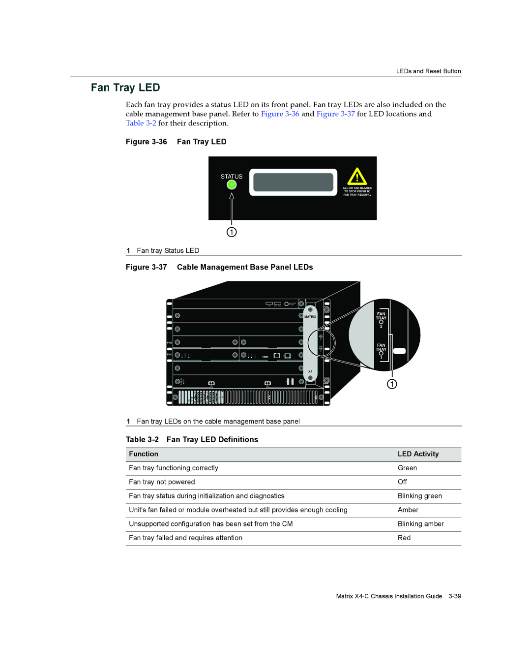
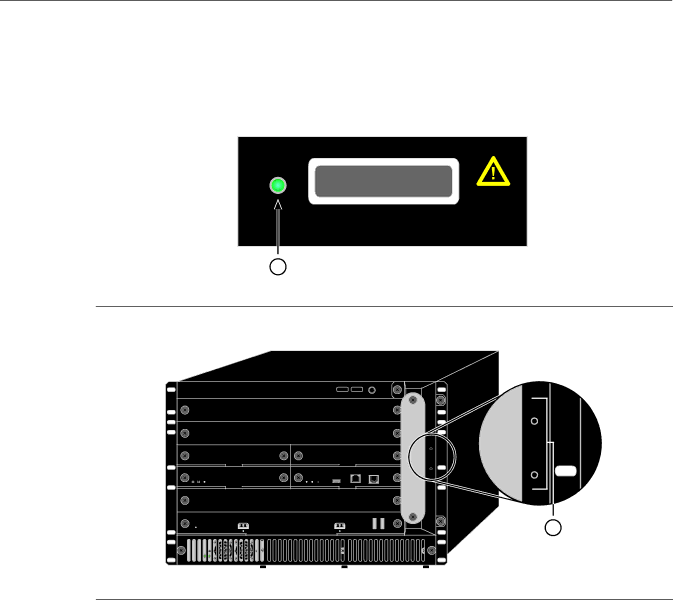
Each fan tray provides a status LED on its front panel. Fan tray LEDs are also included on the cable management base panel. Refer to Figure 3‐36 and Figure 3‐37 for LED locations and Table 3‐2 for their description.
Figure 3-36 Fan Tray LED
STATUS
ALLOW FAN BLADES
TO STOP PRIOR TO
FAN TRAY REMOVAL
1
1Fan tray Status LED
Figure 3-37 Cable Management Base Panel LEDs
|
|
|
|
|
| GROUND |
|
|
|
|
| S/N: | MAC ADD. | STRAP |
|
|
|
|
|
|
| ||
|
|
|
|
|
| MATRIX |
|
|
|
|
|
|
| 4 |
|
|
|
|
|
|
| 3 | FAN |
|
|
|
|
|
|
| TRAY |
|
|
|
|
|
| CM2 | 2 |
FM2 |
|
|
|
|
|
|
|
|
|
|
|
|
|
| FAN |
|
|
|
|
|
|
| TRAY |
|
|
|
|
|
| CM1 | 1 |
FM1 |
|
|
| ETHERNET |
| COM |
|
|
| USB |
|
|
| ||
|
|
|
|
|
| X4 |
|
|
|
|
|
|
| 2 |
|
STATUS |
|
|
|
|
|
| |
X- | TX RX | TX RX |
|
|
| ||
| TX | RX | TX | RX |
|
|
|
FAN
TRAY
2
FAN
TRAY
1
1
1 Fan tray LEDs on the cable management base panel
Table 3-2 Fan Tray LED Definitions
Function | LED Activity |
|
|
Fan tray functioning correctly | Green |
|
|
Fan tray not powered | Off |
|
|
Fan tray status during initialization and diagnostics | Blinking green |
|
|
Unit’s fan failed or module overheated but still provides enough cooling | Amber |
|
|
Unsupported configuration has been set from the CM | Blinking amber |
|
|
Fan tray failed and requires attention | Red |
|
|
Matrix