GE JGBS15, LGB156, LGB116, LGB146, LGB126, RGB526, RGB628, RGB535, RGB530, RGB532, RGB501, RGB525 ⁄ 8 ″

Page 39

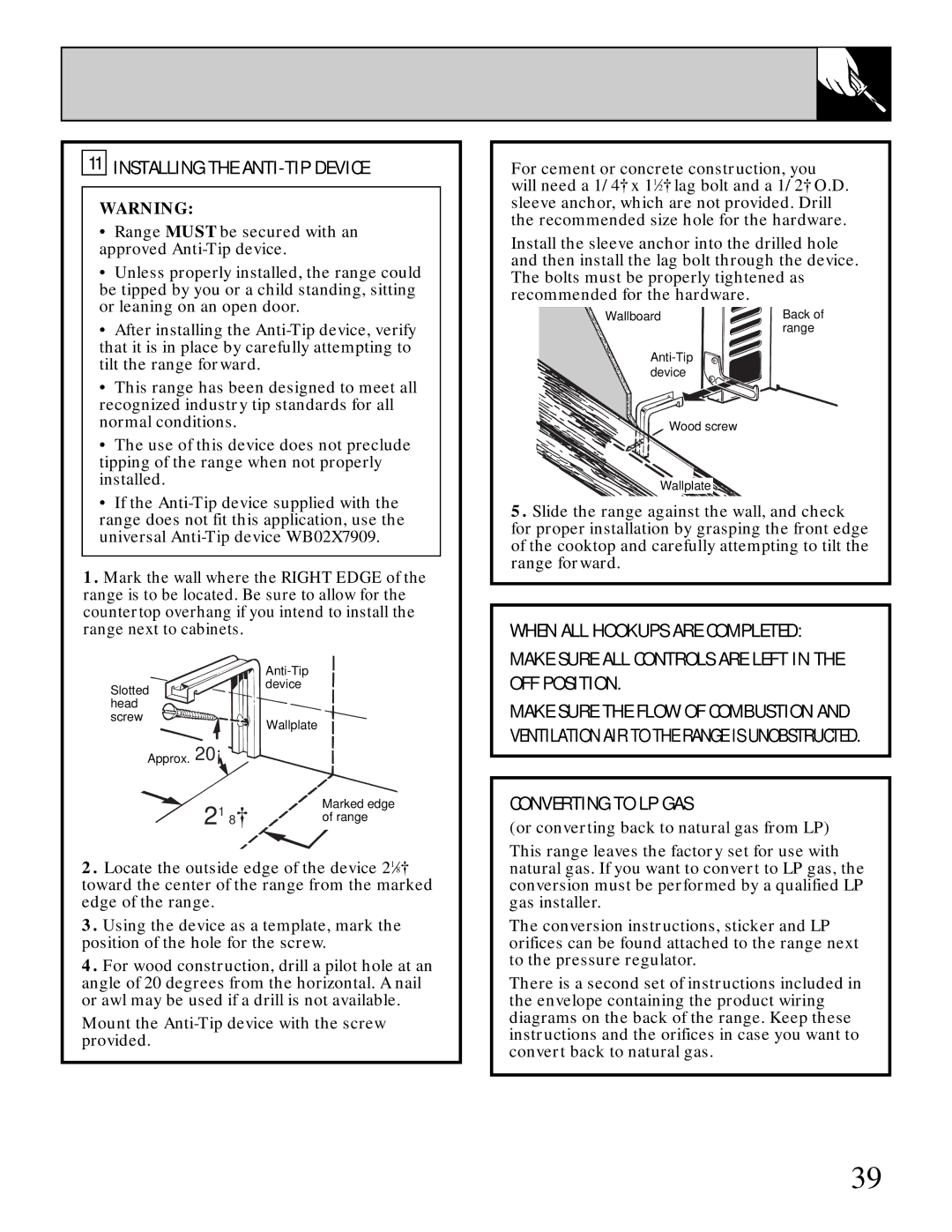
11 INSTALLING THE ANTI-TIP DEVICE

WARNING:

Range MUST be secured with an approved Anti-Tip device.

Unless properly installed, the range could be tipped by you or a child standing, sitting or leaning on an open door.

After installing the Anti-Tip device, verify that it is in place by carefully attempting to tilt the range forward.

This range has been designed to meet all recognized industry tip standards for all normal conditions.

The use of this device does not preclude tipping of the range when not properly installed.

If the Anti-Tip device supplied with the range does not fit this application, use the universal Anti-Tip device WB02X7909.

1.Mark the wall where the RIGHT EDGE of the range is to be located. Be sure to allow for the countertop overhang if you intend to install the range next to cabinets.

Anti-Tip device

Slotted

head

screw

Wallplate

Approx. 20°

218

Marked edge

of range

2.Locate the outside edge of the device 218″ toward the center of the range from the marked edge of the range.

3.Using the device as a template, mark the position of the hole for the screw.

4.For wood construction, drill a pilot hole at an angle of 20 degrees from the horizontal. A nail or awl may be used if a drill is not available.

Mount the Anti-Tip device with the screw provided.

For cement or concrete construction, you will need a 1/4″ x 112″ lag bolt and a 1/2″ O.D. sleeve anchor, which are not provided. Drill the recommended size hole for the hardware.

Install the sleeve anchor into the drilled hole and then install the lag bolt through the device. The bolts must be properly tightened as recommended for the hardware.

Wallboard

Back of


range

Anti-Tip device

Wood screw

Wallplate

5.Slide the range against the wall, and check for proper installation by grasping the front edge of the cooktop and carefully attempting to tilt the range forward.

WHEN ALL HOOKUPS ARE COMPLETED: MAKE SURE ALL CONTROLS ARE LEFT IN THE OFF POSITION.

MAKE SURE THE FLOW OF COMBUSTION AND VENTILATION AIR TO THE RANGE IS UNOBSTRUCTED.

CONVERTING TO LP GAS

(or converting back to natural gas from LP)

This range leaves the factory set for use with natural gas. If you want to convert to LP gas, the conversion must be performed by a qualified LP gas installer.

The conversion instructions, sticker and LP orifices can be found attached to the range next to the pressure regulator.

There is a second set of instructions included in the envelope containing the product wiring diagrams on the back of the range. Keep these instructions and the orifices in case you want to convert back to natural gas.

39
Image 39
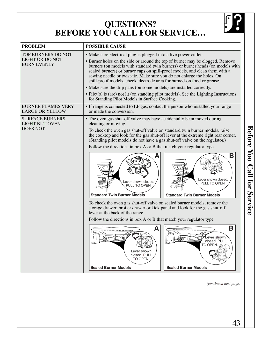
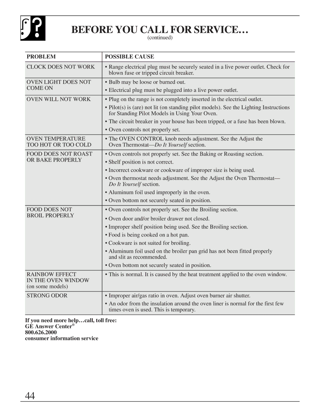
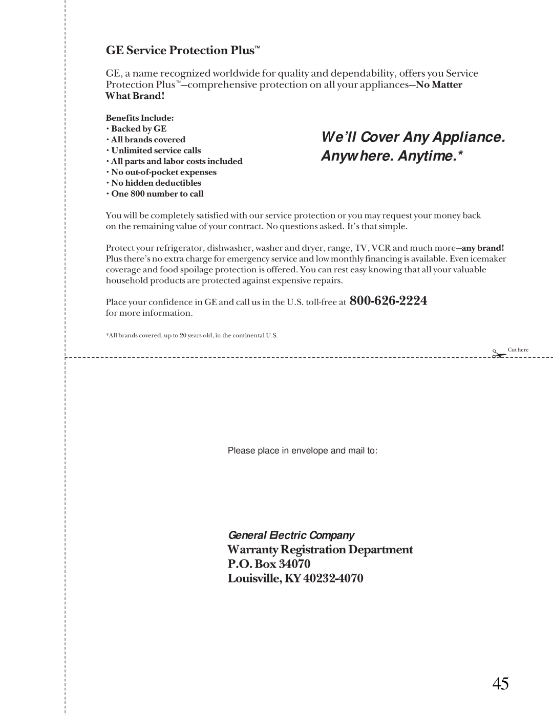
Contents Operating Instructions, Tips Safety InstructionsHelp US Help YOU… If YOU Need ServiceImportant Safety Instructions When You Get Your RangeUsing Your Range Do not allow anyone to climb, stand or Surface CookingCleaning Your Range Save These INSTRUCTIONS5Baking, Broiling and Roasting Features and appearance vary Features of Your RangeBroiler Pan and Grid SeeSurface Burners, Grates and Drip Pans on some models Oven ControlTo Light a Surface Burner Surface CookingSurface Burner Controls Before Lighting a BurnerHow to Select Flame Size Top-of-Range CookwareDo not use a wok on any other support ring Display Clock While Timer Is Operating Clock and TimerTo Set the Timer To Change or Cancel the Timer SettingUsing Your Oven Oven Shelves Shelf PositionsOven Vents Type of Food Shelf Position How to Set Your Range for BakingBaking To avoid possible burns, place the shelvesCookies Pan PlacementPreheating Baking GuidesDon’t Peek PiesCakes Baking PansTo Adjust the Thermostat Adjust the Oven ThermostatRoasting Frozen Roasts Questions and AnswersWhy is my roast crumbling when I try to carve it? Roasting GuideShould I salt the meat before broiling? Why are my meats not turning out as brown as they should?Broiling Use of Aluminum FoilGround Beef Broiling GuideStandard Twin Burners on some models Care and CleaningFor proper ignition Sealed Burner Assemblies on some modelsBurner Grates Cooktop SurfaceOven Bottom Broiler Pan and Grid Oven Light Bulb on some modelsControl Panel and Knobs Removable Broiler Drawer on some modelsOven Air Vents Removable Storage Drawer on some modelsRemovable Kick Panel on some models Outside of door Lift-Off Oven DoorOven bottom has a porcelain enamel finish For Your Safety Installation InstructionsImportant Safety Instructions General Provide Adequate GAS Supply Rigid Pipe Hookup for Models Equipped with Sealed Burners Connect the Range to GASExtension Cord Cautions Electrical Connections on some modelsGrounding Electrical RequirementsElectric Disconnect Electrical ConnectionsAdjust the Surface Burner Pilots if Necessary Light the Surface Burner PilotsLight the Oven Pilot Yellow flames Light the PilotsQuality of Flames Electric Ignition ModelsTo remove the oven bottom To remove the broiler drawer Leveling the Range⁄ 8 ″ Page Page Page Problem Possible Cause QUESTIONS? Before YOU Call for SERVICE…Do It Yourself section We’ll Cover Any Appliance. Anywhere. Anytime Consumer Product Ownership Registration We’ll Be There Warranty