6. Specification of Connection
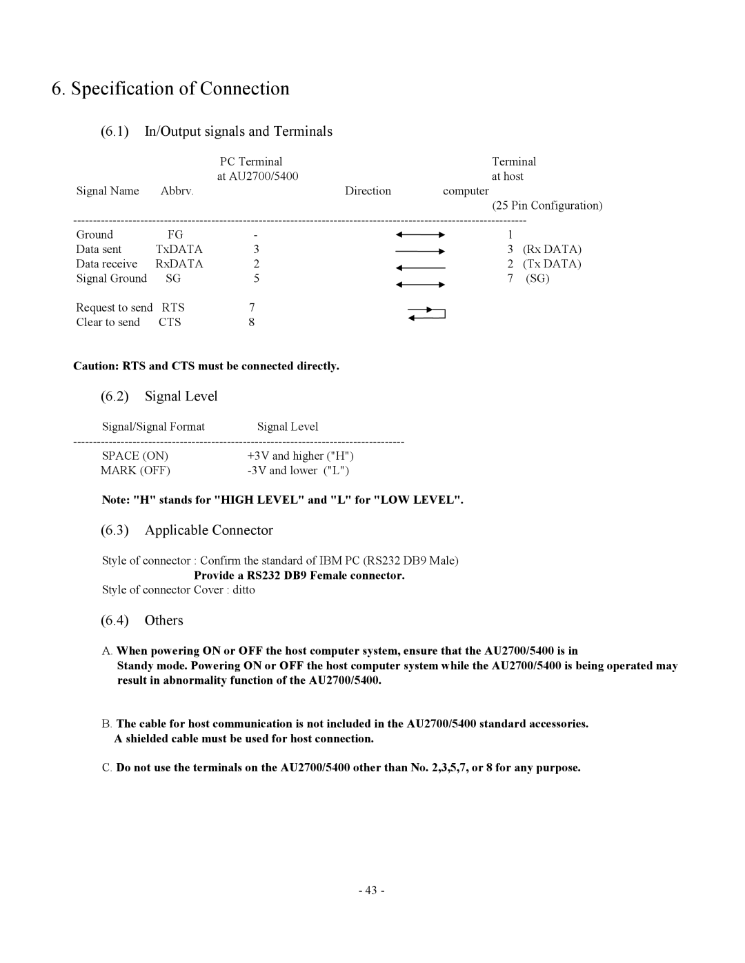
(6.1) In/Output signals and Terminals
|
| PC Terminal |
|
|
|
|
| Terminal | |
|
| at AU2700/5400 |
|
|
|
|
| at host | |
Signal Name | Abbrv. |
| Direction |
|
|
| computer |
| |
|
|
|
|
|
|
|
| (25 Pin Configuration) | |
Ground | FG | - |
| 1 |
| ||||
Data sent | TxDATA | 3 |
| 3 | (Rx DATA) | ||||
Data receive | RxDATA | 2 |
|
| 2 | (Tx DATA) | |||
Signal Ground | SG | 5 |
| 7 | (SG) | ||||
Request to send | RTS | 7 |
|
|
|
|
|
|
|
|
|
|
|
|
|
| |||
Clear to send | CTS | 8 |
|
|
|
|
|
|
|
Caution: RTS and CTS must be connected directly.
(6.2) Signal Level
Signal/Signal Format Signal Level
SPACE (ON) | +3V and higher ("H") |
MARK (OFF) |
Note: "H" stands for "HIGH LEVEL" and "L" for "LOW LEVEL".
(6.3) Applicable Connector
Style of connector : Confirm the standard of IBM PC (RS232 DB9 Male)
Provide a RS232 DB9 Female connector.
Style of connector Cover : ditto
(6.4) Others
A. When powering ON or OFF the host computer system, ensure that the AU2700/5400 is in
Standy mode. Powering ON or OFF the host computer system while the AU2700/5400 is being operated may result in abnormality function of the AU2700/5400.
B. The cable for host communication is not included in the AU2700/5400 standard accessories.
A shielded cable must be used for host connection.
C. Do not use the terminals on the AU2700/5400 other than No. 2,3,5,7, or 8 for any purpose.
- 43 -