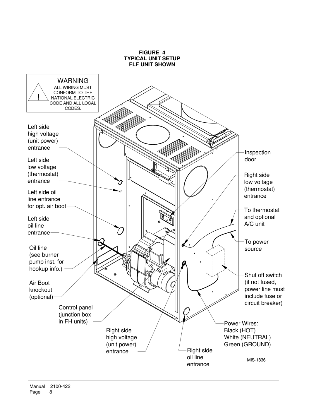
WARNING
ALL WIRING MUST
CONFORM TO THE ! NATIONAL ELECTRIC
CODE AND ALL LOCAL
CODES.
FIGURE 4
TYPICAL UNIT SETUP
FLF UNIT SHOWN
Left side high voltage (unit power) entrance
Left side low voltage (thermostat) entrance
Left side oil line entrance for opt. air boot
Left side oil line entrance
Oil line (see burner pump inst. for hookup info.)
Air Boot knockout (optional)
Control panel (junction box in FH units)
Right side high voltage
(unit power)
entranceRight side oil line
entrance
Inspection door
Right side low voltage (thermostat) entrance
To thermostat and optional A/C unit
![]() To power source
To power source
![]() Shut off switch (if not fused, power line must include fuse or circuit breaker)
Shut off switch (if not fused, power line must include fuse or circuit breaker)
Power Wires:
Black (HOT)
White (NEUTRAL)
Green (GROUND)
Manual
Page 8