L
i
n e d
C h i m n e y
Clean-out Door (keep closed)
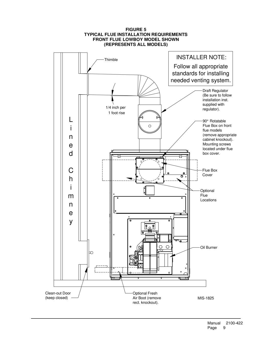
FIGURE 5
TYPICAL FLUE INSTALLATION REQUIREMENTS
FRONT FLUE LOWBOY MODEL SHOWN
(REPRESENTS ALL MODELS)
Thimble | INSTALLER NOTE: | |
| ||
| Follow all appropriate | |
| standards for installing | |
| needed venting system. | |
| Draft Regulator | |
| (Be sure to follow | |
| installation inst. | |
1/4 inch per | supplied with | |
regulator). | ||
1 foot rise | ||
| ||
| 90° Rotatable | |
| Flue Box on front | |
| flue models | |
| (remove appropriate | |
| cabinet knockout). | |
| Mounting screws | |
| located under flue | |
| box cover. | |
| Flue Box | |
| Cover |
Optional
Flue
Locations
Oil Burner
Optional Fresh
Air Boot (removeMIS-1825 rect. knockout).
Manual
