INSTALLATION and OPERATING INSTRUCTIONS
EQUIPMENT SELECTION
An accurate heating load calculation must be conducted using American Society of Heating, Refrigeration and Air Conditioning Engineers (ASHRAE) or Air Conditioning Contractors of America (ACCA) manuals. Do not add a large safety factor above the calculated value. If the calculated heating load requirement exceeds the heating capacity rating of a given model, use only the next larger size available. Never increase by any more than absolutely necessary based upon available equipment heating capacities. Always select based upon heat capacity (output), never use input capacities.
NOTE: It is the personal responsibility and obligation of the purchaser to contract a qualified installer to assure that installation is adequate and is in conformance with governing codes and ordinances.
LOCATING THE FURNACE
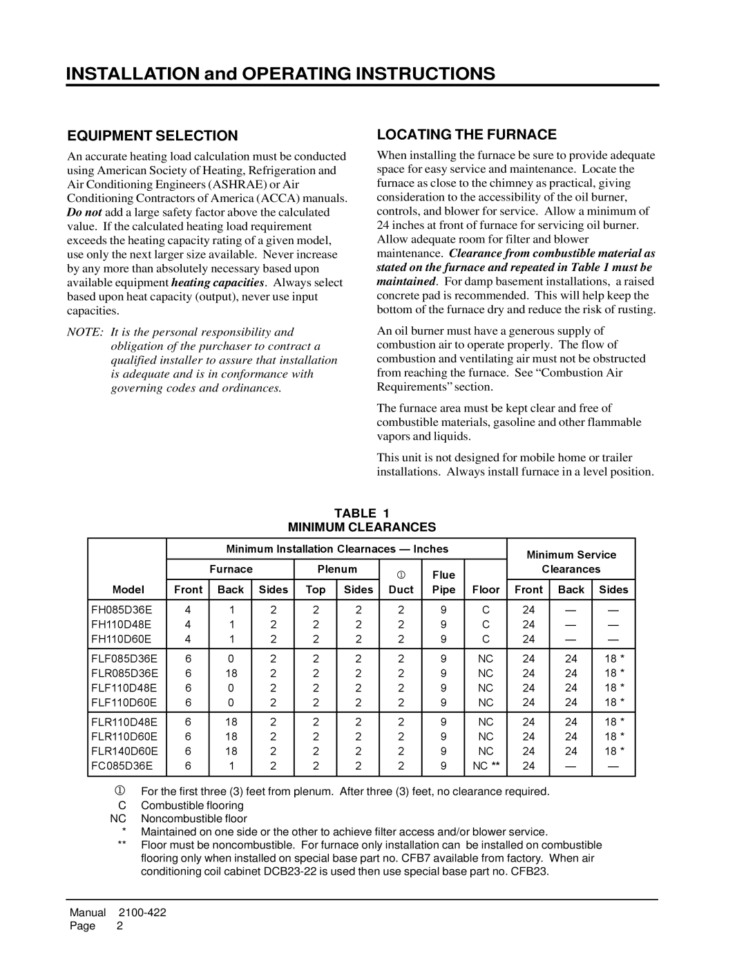
When installing the furnace be sure to provide adequate space for easy service and maintenance. Locate the furnace as close to the chimney as practical, giving consideration to the accessibility of the oil burner, controls, and blower for service. Allow a minimum of 24 inches at front of furnace for servicing oil burner. Allow adequate room for filter and blower maintenance. Clearance from combustible material as stated on the furnace and repeated in Table 1 must be maintained. For damp basement installations, a raised concrete pad is recommended. This will help keep the bottom of the furnace dry and reduce the risk of rusting.
An oil burner must have a generous supply of combustion air to operate properly. The flow of combustion and ventilating air must not be obstructed from reaching the furnace. See “Combustion Air Requirements” section.
The furnace area must be kept clear and free of combustible materials, gasoline and other flammable vapors and liquids.
This unit is not designed for mobile home or trailer installations. Always install furnace in a level position.
TABLE 1
MINIMUM CLEARANCES
|
| Minimum Installation Clearnaces — Inches |
| Minimum Service | ||||||||
|
| Furnace |
| Plenum | 1 | Flue |
| Clearances | ||||
|
|
|
|
|
|
|
|
|
|
| ||
Model | Front | Back |
| Sides | Top | Sides | Duct | Pipe | Floor | Front | Back | Sides |
|
|
|
|
|
|
|
|
|
|
|
|
|
FH085D36E | 4 | 1 |
| 2 | 2 | 2 | 2 | 9 | C | 24 | — | — |
FH110D48E | 4 | 1 |
| 2 | 2 | 2 | 2 | 9 | C | 24 | — | — |
FH110D60E | 4 | 1 |
| 2 | 2 | 2 | 2 | 9 | C | 24 | — | — |
FLF085D36E | 6 | 0 |
| 2 | 2 | 2 | 2 | 9 | NC | 24 | 24 | 18 * |
FLR085D36E | 6 | 18 |
| 2 | 2 | 2 | 2 | 9 | NC | 24 | 24 | 18 * |
FLF110D48E | 6 | 0 |
| 2 | 2 | 2 | 2 | 9 | NC | 24 | 24 | 18 * |
FLF110D60E | 6 | 0 |
| 2 | 2 | 2 | 2 | 9 | NC | 24 | 24 | 18 * |
|
|
|
|
|
|
|
|
|
|
|
|
|
FLR110D48E | 6 | 18 |
| 2 | 2 | 2 | 2 | 9 | NC | 24 | 24 | 18 * |
FLR110D60E | 6 | 18 |
| 2 | 2 | 2 | 2 | 9 | NC | 24 | 24 | 18 * |
FLR140D60E | 6 | 18 |
| 2 | 2 | 2 | 2 | 9 | NC | 24 | 24 | 18 * |
FC085D36E | 6 | 1 |
| 2 | 2 | 2 | 2 | 9 | NC ** | 24 | — | — |
|
|
|
|
|
|
|
|
|
|
|
|
|
jFor the first three (3) feet from plenum. After three (3) feet, no clearance required. C Combustible flooring
NC Noncombustible floor
*Maintained on one side or the other to achieve filter access and/or blower service.
**Floor must be noncombustible. For furnace only installation can be installed on combustible flooring only when installed on special base part no. CFB7 available from factory. When air conditioning coil cabinet
Manual
Page 2