Make sure that the PGND cable has been properly connected before powering on the switch.
Connecting an RPS DC Power Cord
The 3Com Baseline Switch
Step1 Connect one end of the supplied PGND cable to the grounding screw on the rear panel of the chassis and the other end to the ground as near as possible.
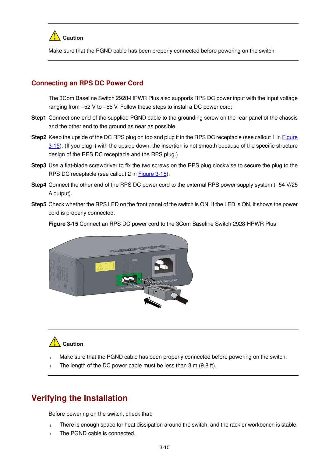
Step2 Keep the upside of the DC RPS plug on top and plug it in the RPS DC receptacle (see callout 1 in Figure
Step3 Use a
Step4 Connect the other end of the RPS DC power cord to the external RPS power supply system
Step5 Check whether the RPS LED on the front panel of the switch is ON. If the LED is ON, it shows the power cord is properly connected.
Figure 3-15 Connect an RPS DC power cord to the 3Com Baseline Switch 2928-HPWR Plus
z
z
Make sure that the PGND cable has been properly connected before powering on the switch. The length of the DC power cable must be less than 3 m (9.8 ft).
Verifying the Installation
Before powering on the switch, check that:
z
z
There is enough space for heat dissipation around the switch, and the rack or workbench is stable. The PGND cable is connected.