4 Initial Power-On
Setting Up the Configuration Environment
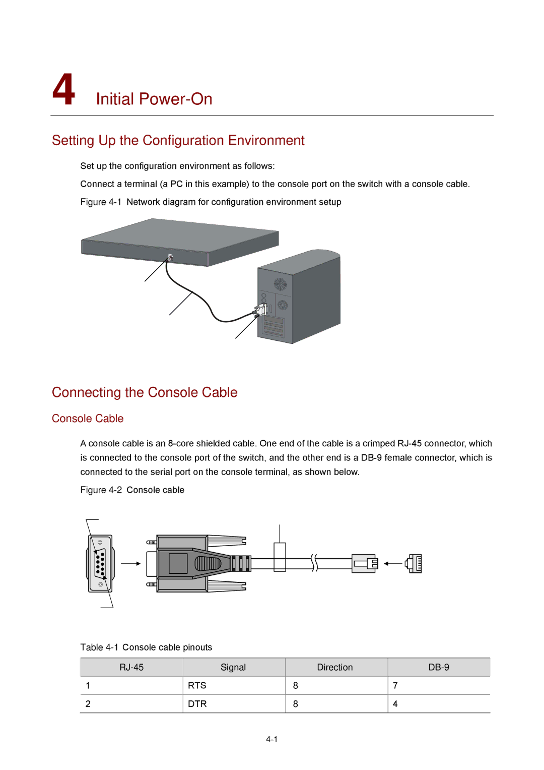
Set up the configuration environment as follows:
Connect a terminal (a PC in this example) to the console port on the switch with a console cable.
Figure 4-1 Network diagram for configuration environment setup
Connecting the Console Cable
Console Cable
A console cable is an
Figure 4-2 Console cable
Table 4-1 Console cable pinouts
| Signal |
| Direction |
|
1 | RTS |
| ← | 7 |
|
|
|
|
|
2 | DTR |
| ← | 4 |
|
|
|
|
|
|
|
|
|