Manuals
/
3Com
/
Computer Equipment
/
Switch
3Com
5108M-TP
manual
BASE-T Module Faceplate and ONline System Concentrator
Models:
5108M-TP
1
19
66
66
Download
66 pages
24.79 Kb
16
17
18
19
20
21
22
23
Troubleshooting
Specs
Install
Indicators
Connecting Twisted Pair Cables
Accessing the 3Com MIB
Twisted Pair Connectors
Precautionary Procedures
Channel Select Switch Settings
How to
Page 19
Image 19
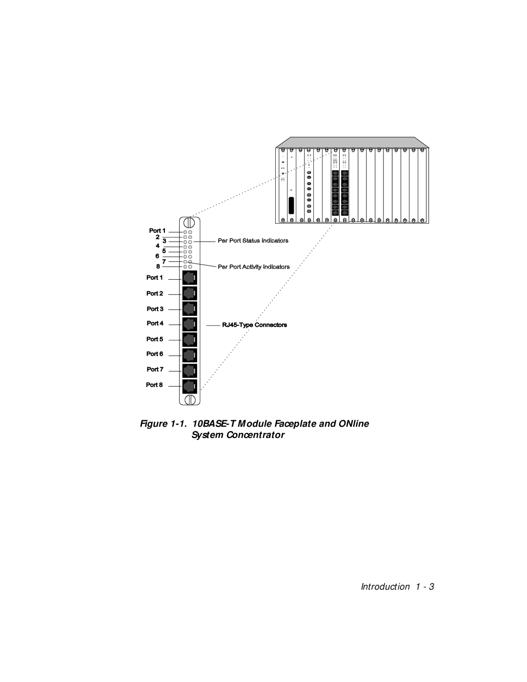
Figure
1-1.
10BASE-T
Module Faceplate and ONline System Concentrator
Introduction 1 - 3
Page 18
Page 20
Page 19
Image 19
Page 18
Page 20
Contents
ONline Ethernet 10BASE-T Module User’s Guide
Ii ONline Ethernet 10BASE-T Module User’s Guide
ONline Ethernet 10BASE-T Module User’s Guide
Iv ONline Ethernet 10BASE-T Module User’s Guide
Contents
Installing and Operating the Module
Figures
Viii ONline Ethernet 10BASE-T Module User’s Guide
Tables
Page
Audience
How to Use This Guide
Structure of This Guide
Convention Indicates Example
Document Conventions
Usr/snm/agents
Related Documents
Reference Documents
3Com Documents
Page
ONline Ethernet 10BASE-T Module
Introduction
Indicators
BASE-T Module Faceplate and ONline System Concentrator
Interpretation of the 10BASE-T Module LEDs
Dip Switches
LED Name Color State Indicates
Dip Switch SW1 Port Status
Dip Switch SW1 Settings and Interpretations
Dip Switch SW3 Crossover Mode, Channel Select, Squelch
Squelch Mode Switch
Dip Switch SW3 Settings for Switches 1
Switch Function Factory Switch Setting Default Off
Crossover Mode Switch
Channel Select Switch Settings
Switch Channel Selection
Dip Switch SW3 Settings and Interpretations for Switches 2
Dip Switch SW6 Settings and Interpretations
Related Features
Enable
Channel Check Codes
LED State Channel Configuration
Page
Designing and ExpandingtheNetwork
Basic Network Rules
Understanding the General Rules
Rule Definition Recommendations/Notes
Seven Basic Network Rules
Certain LAN devices
Seven Basic Network Rules
LAN Product Equivalent Distances
LAN Equivalence
LAN Product Equivalent Distance meters
Fiber Backbone, Twisted Pair To-The-Desk
Fiber Backbone, Twisted Pair To-The-Desk Example
Sample Configuration Distance Calculation
Unshielded Twisted Pair High Squelch Low Squelch
Maximum Link Distance on Twisted Pair
Shielded Twisted Pair High Squelch Low Squelch IBM Type
Unshielded Twisted Pair Network
Twisted Pair Backbone, Twisted Pair To-The-Desk
Redundant Links
Redundant Twisted Pair Configuration
Page
Patch Panels
Precautionary Procedures
Installing and Operating the Module
Installation Procedures
Unpacking Procedures
Installing a 10BASE-T Module
BASE-T Module Cable Connection
Troubleshooting
Troubleshooting
Troubleshooting With the Port Status LEDs
Troubleshooting With the Status LEDs
Troubleshooting With the Port Status LEDs
Troubleshooting With the Port Status LEDs
LED Name
Troubleshooting With the Activity LEDs
Troubleshooting With the Port Activity LEDs
Possible Problem Troubleshooting State Solutions
Technical Assistance
Electrical Specifications
ONline Ethernet 10BASE-T Module Specifications
Mechanical Specifications
Environmental Specifications
General Specifications
Twisted Pair Connectors
Twisted Pair Connectors and Cables
Twisted Pair Cables
Figure A-1. RJ45 Connector Pin-outs
Connecting Twisted Pair Cables
Page
On-line Technical Support
Technical Support
Email Technical Support
Support from Your Network Supplier
World Wide Web Site
Support from 3Com
Returning Products for Repair
Accessing the 3Com MIB
3Com Technical Publications
Page
Index
MIB, B-4
Top
Page
Image
Contents