2
SYSTEM DESCRIPTION
Overview |
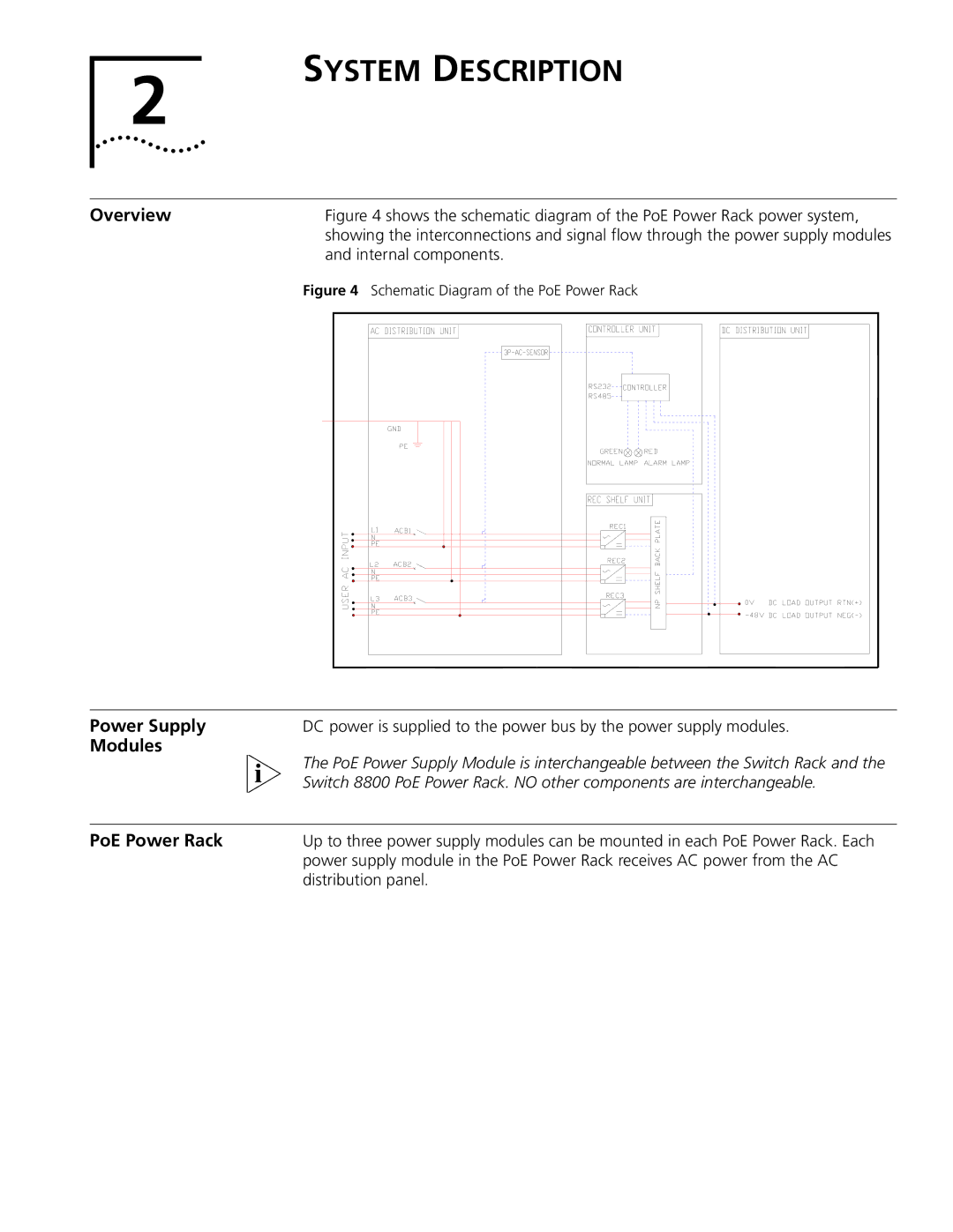
| Figure 4 shows the schematic diagram of the PoE Power Rack power system, | |||||||||||||||
|
| showing the interconnections and signal flow through the power supply modules | |||||||||||||||
|
| and internal components. | |||||||||||||||
| Figure 4 Schematic Diagram of the PoE Power Rack | ||||||||||||||||
|
|
|
|
|
|
|
|
|
|
|
|
|
|
|
|
|
|
|
|
|
|
|
|
|
|
|
|
|
|
|
|
|
|
|
|
|
|
|
|
|
|
|
|
|
|
|
|
|
|
|
|
|
|
|
|
|
|
|
|
|
|
|
|
|
|
|
|
|
|
|
|
|
|
|
|
|
|
|
|
|
|
|
|
|
|
|
|
|
|
|
|
|
|
|
|
|
|
|
|
|
|
|
|
|
|
|
|
|
|
|
|
|
|
|
|
|
|
|
|
|
|
|
|
|
|
|
|
|
|
|
|
|
|
|
|
|
|
|
|
|
|
|
|
|
|
|
|
|
|
|
|
|
|
|
|
|
|
|
|
|
|
|
|
|
|
|
|
|
|
|
|
|
|
|
|
|
|
|
|
|
|
|
|
|
|
|
|
|
|
|
|
|
|
|
|
|
|
|
|
|
|
|
|
|
|
|
|
|
|
|
|
|
|
|
|
|
|
|
|
|
|
|
|
|
|
|
|
|
|
|
|
|
|
|
|
|
|
|
|
|
|
|
|
|
|
|
|
|
|
|
|
|
|
|
|
|
|
|
|
|
|
|
|
|
|
|
|
|
|
|
|
|
|
|
|
|
|
|
|
|
|
|
|
|
|
|
|
Power Supply | DC power is supplied to the power bus by the power supply modules. |
Modules | The PoE Power Supply Module is interchangeable between the Switch Rack and the |
| |
| Switch 8800 PoE Power Rack. NO other components are interchangeable. |
|
|
PoE Power Rack | Up to three power supply modules can be mounted in each PoE Power Rack. Each |
| power supply module in the PoE Power Rack receives AC power from the AC |
| distribution panel. |
