A member of the 3Com SuperStack II System
SuperStack II Hub 1000 SX
User Guide
3Com Corporation 5400 Bayfront Plaza Santa Clara, California
UNITED STATES GOVERNMENT LEGENDS
ABOUT THIS GUIDE 1 INTRODUCTION
CONTENTS
2 INSTALLING THE HUB
POST Messages
A USING THE CONSOLE PORT
3 MAKING CONNECTIONS
SPECIFICATIONS
GLOSSARY INDEX 3COM CORPORATION LIMITED WARRANTY
TECHNICAL SUPPORT
FCC CLASS A VERIFICATION STATEMENT
Page
FIGURES
Page
TABLES
Port Configuration Menu
Page
ABOUT THIS GUIDE
Icon
Notice Type
Description
Commands
SETDEFAULT !0 -IP NETaddr =
Menu commands
and buttons
General Description
INTRODUCTION
Hub 1000 SX
Downlinks
and Uplink
Full-Duplex
Operation
Flow Control
Features and
Functions
INSTALLING THE HUB
SuperStack II Hub 1000 SX User Guide
Hub Description The hub’s front and rear panels are shown in Figure
Installing and
Connecting the Hub
4 Repeat steps 2 and 3 for the other side of the hub
Connector
Table 2-1 Downlink Connections
Maximum Cable
Type
Table 2-2 Hub 1000 SX Indicators
Indicator
Color
Status
The gigabit interface connector GBIC port on the rear panel of the
Connecting a
GBIC Module
Using Optional
Power Systems
Power Modules
Cabling Options
A hub connects to a UPS unit through the hub’s AC power cord
Table 2-4 Advanced RPS Configuration Options
You can connect a UPS unit to an Advanced RPS unit as long as you do not exceed the maximum wattage 325 watts for the UPS unit. To verify that the UPS unit’s maximum wattage is not exceeded, calculate the total power consumption of all units connected to the Advanced RPS. If the result is less than 325 watts, your configuration is safe if the result is greater than 325 watts, then there are too many units connected to the Advanced RPS
Page
MAKING CONNECTIONS
Table 3-1 Gigabit Ethernet Maximum Cable Lengths
Power Workgroup
Aggregating
Servers
connecting to the network backbone. See Figure
You can use the Hub 1000 SX downlinks to aggregate 10/100 Mbps
Switches
The Hub 1000 SX does not support bandwidth aggregation trunking
Figure 3-3 Aggregated Switches Connection
3-4 CHAPTER 3 MAKING CONNECTIONS
The best use of the hub uplink is as a backbone connection to a 3Com
Connecting
Figure 3-4 Mixed Connection
Figure 3-6 Uplink Connection to a 10/100 Mbps Switch
Table 3-2 Troubleshooting Tips
Symptom
Solution
USING THE CONSOLE PORT
Connecting the
With Power
Requirements
Console Port
from power
To connect the console port when the hub is disconnected
Connecting the Console Port A-3
Disconnected
After 4 minutes of inactivity, the CLI logs off automatically
Logging On
message, return the hub to the supplier
Password
Port Settings
Changing the
Configuring
To display the Port Configuration menu
Configuring Port Settings
Table A-2 Port Configuration Menu
A-8 APPENDIX A USING THE CONSOLE PORT
Configuring Port Settings
and be configured to receive pause frames
Configuring Port Settings A-11
Displaying
Hub Status
matrix, Y indicates yes and n indicates no. See Table A-3
Table A-3 Hub Status Information
Displaying Hub Status A-13
Restoring the Factory Default Settings
A-14 APPENDIX A USING THE CONSOLE PORT
Updating the
Firmware Image
entering option
Checking the
Xmodem-CRC To transfer the firmware image file
log in again. To restart the file transfer, repeat steps 6 and
during a firmware update, the CLI displays the following message
Logging Off
While saving port settings or
Table A-4 File Transfer Error Messages
Table A-5 Fatal Error Messages
Environmental Operating Ranges
SPECIFICATIONS
Physical Dimensions
Page
Services
Board Service
TECHNICAL SUPPORT
Online Technical
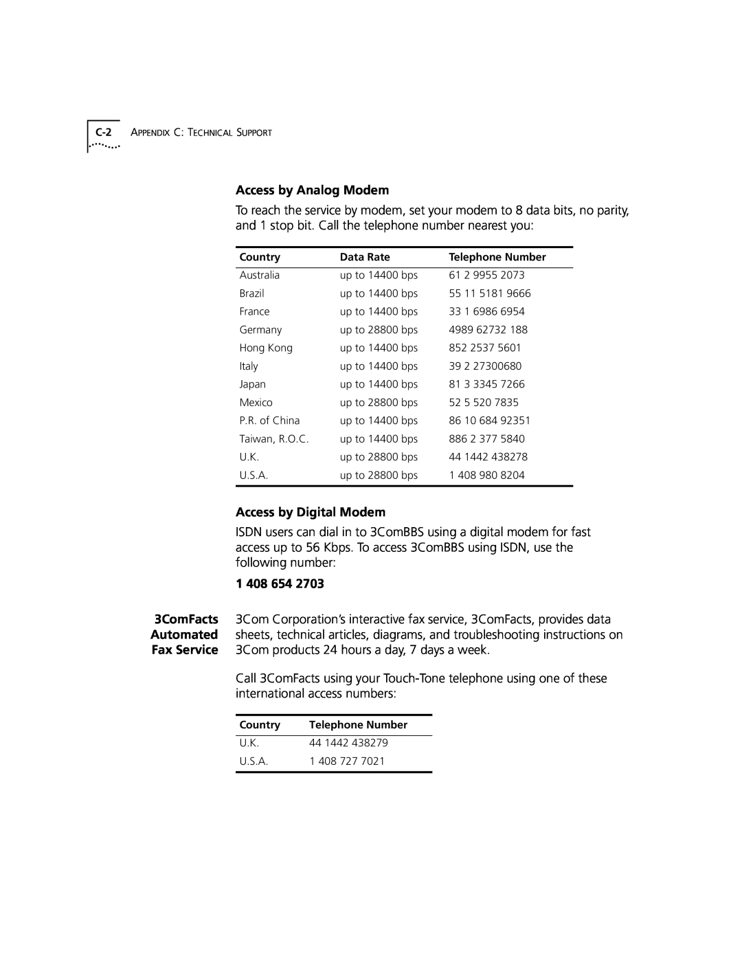
Access by Analog Modem
Access by Digital Modem
1 408 654
C-2 APPENDIX C TECHNICAL SUPPORT
Local access numbers are available within the following countries
Santa Clara, California
Czech Republic/Slovak
Central European HQ
305 261 3266 Miami, Florida
To obtain an RMA number, call or fax
Page
GLOSSARY
Carrier Sense Multiple Access/Collision Detection. Channel access
cable is based on CSMA/CD Carrier Sense Multiple Access/Collision
access method
transmission of light signals
IEEE
incoming
flow control
Mbps
control. See also asymmetric flow control, flow control, pause frame
Numbers
Symbols
INDEX
Page
Switch 9300 3-2, 3-3
Page
3Com Corporation LIMITED WARRANTY
STANDARD WARRANTY SERVICE
HARDWARE
SOFTWARE
GOVERNING LAW
FCC CLASS A VERIFICATION STATEMENT
LIMITATION OF LIABILITY