A.O. Smith Residential Power Vent Gas Water Heaters with Hot Surface Ignition The discharge pipe

Models: Residential Power Vent Gas Water Heaters with Hot Surface Ignition

1 40
Download 40 pages 16.21 Kb
Page 12
Image 12
Installing the New Water Heater (cont’d)

Installing the New Water Heater (cont’d)

Temperature-Pressure Relief Valve

Temperature-Pressure Relief Valve WARNING

At the time of manufacture this water heater was provided with a combination temperature-pressure relief valve certi- fied by a nationally recognized testing laboratory that main- tains periodic inspection of production of listed equipment or materials, as meeting the requirements for Relief Valves and Automatic Gas Shutoff Devices for Hot Water Supply Systems, and the current edition of ANSI Z21.22 • CSA 4.4 and the code requirements of ASME. If replaced, the valve must meet the requirements of local codes, but not less than a combination temperature and pressure relief valve certi- fied as meeting the requirements for Relief Valves and Automatic Gas Shutoff Devices for Hot Water Supply Systems, ANSI Z21.22 • CSA 4.4 by a nationally recognized testing laboratory that maintains periodic inspection of pro- duction of listed equipment or materials.

The valve must be marked with a maximum set pressure not to exceed the marked hydrostatic working pressure of the water heater (150 lbs./sq. in.) and a discharge capacity not less than the water heater input rate as shown on the model rating plate. (Electric heaters - watts divided by 1000 x 3412) equal BTU/Hr. rate.

Your local jurisdictional authority, while mandating the use of a temperature-pressure relief valve complying with ANSI Z21.22 • CSA 4.4 and ASME, may require a valve model dif- ferent from the one furnished with the water heater.

Compliance with such local requirements must be satisfied by the installer or end user of the water heater with a local- ly prescribed temperature-pressure relief valve installed in the designated opening in the water heater in place of the factory furnished valve.

For safe operation of the water heater, the relief valve must not be removed from it’s designated opening or plugged. The temperature-pressure relief valve must be installed directly into the fitting of the water heater designated for the relief valve. Position the valve downward and provide tubing so that any discharge will exit only within 6 inches above, or at any distance below the structural floor. Be cer- tain that no contact is made with any live electrical part. The discharge opening must not be blocked or reduced in size under any circumstances. Excessive length, over 30 feet, or use of more than four elbows can cause restriction and reduce the discharge capacity of the valve.

No valve or other obstruction is to be placed between the relief valve and the tank. Do not connect tubing directly to discharge drain unless a 6air gap is provided. To prevent bodily injury, hazard to life, or property damage, the relief valve must be allowed to discharge water in quantities should circumstances demand. If the discharge pipe is not connected to a drain or other suitable means, the water flow may cause property damage.

The discharge pipe:

—Must not be smaller in size than the outlet pipe size of the valve, or have any reducing couplings or other restriction.

—Must not be plugged or blocked.

—Must be of material listed for hot water distribution. —Must be installed so as to allow complete drainage of both

the temperature-pressure relief valve, and the discharge pipe.
—Must terminate at an adequate drain.

—Must not have any valve between the relief valve and tank.

The discharge pipe: WARNING

The temperature-pressure relief valve must be manually operated at least once a year. Caution should be taken to ensure that (1) no one is in front of or around the out- let of the temperature-pressure relief valve discharge line, and (2) the water manually discharged will not cause any bodily injury or property damage because the water may be extremely hot.

If after manually operating the valve, it fails to com- pletely reset and continues to release water, immedi- ately close the cold water inlet to the water heater, fol- low the draining instructions, and replace the tempera
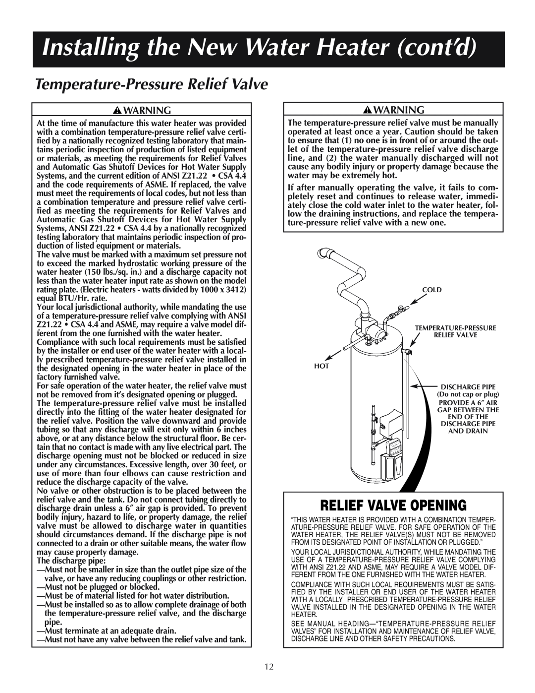
- ture-pressure relief valve with a new one.

COLD

TEMPERATURE-PRESSURE

RELIEF VALVE

HOT

the temperature-pressure relief valve, and the discharge pipe. DISCHARGE PIPE (Do not cap or plug)

PROVIDE A 6AIR

GAP BETWEEN THE

END OF THE

DISCHARGE PIPE

AND DRAIN

RELIEF VALVE OPENING

“THIS WATER HEATER IS PROVIDED WITH A COMBINATION TEMPER- ATURE-PRESSURE RELIEF VALVE. FOR SAFE OPERATION OF THE WATER HEATER, THE RELIEF VALVE(S) MUST NOT BE REMOVED FROM ITS DESIGNATED POINT OF INSTALLATION OR PLUGGED.”

YOUR LOCAL JURISDICTIONAL AUTHORITY, WHILE MANDATING THE USE OF A TEMPERATURE-PRESSURE RELIEF VALVE COMPLYING WITH ANSI Z21.22 AND ASME, MAY REQUIRE A VALVE MODEL DIF- FERENT FROM THE ONE FURNISHED WITH THE WATER HEATER.

COMPLIANCE WITH SUCH LOCAL REQUIREMENTS MUST BE SATIS- FIED BY THE INSTALLER OR END USER OF THE WATER HEATER WITH A LOCALLY PRESCRIBED TEMPERATURE-PRESSURE RELIEF VALVE INSTALLED IN THE DESIGNATED OPENING IN THE WATER HEATER.

SEE MANUAL HEADING—“TEMPERATURE-PRESSURE RELIEF VALVES” FOR INSTALLATION AND MAINTENANCE OF RELIEF VALVE, DISCHARGE LINE AND OTHER SAFETY PRECAUTIONS.

12

Page 12
Image 12
A.O. Smith Residential Power Vent Gas Water Heaters with Hot Surface Ignition Installing the New Water Heater cont’d