Locating the New Water Heater (cont’d)
Facts to Consider About the Location (cont’d)
![]() WARNING
WARNING
Propellants of aerosol sprays and volatile compounds, (cleaners, chlorine based chemicals, refrigerants, etc.) in addition to being highly flammable in many cases, will also change to corrosive hydrochloric acid when exposed to the combustion products of the water heater. The results can be hazardous, and also cause product failure.
![]() WARNING
WARNING
This water heater must not be installed directly on carpeting. Carpeting must be protected by a metal or wood panel beneath the appliance extending beyond the full width and depth of the appliance by at least 3 inches (76.2mm) in any direction, or if the appliance is installed in an alcove or clos- et, the entire floor must be covered by the panel. Failure to heed this warning may result in a fire hazard.
![]() WARNING
WARNING
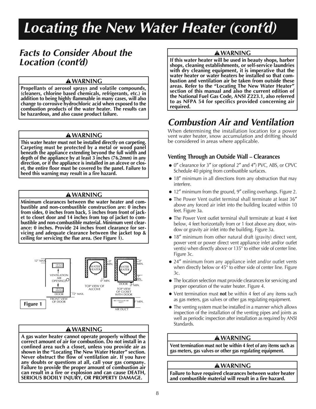
Minimum clearances between the water heater and com- bustible and
12" MAX. |
| 6" MIN. | 0" |
|
| 0" | |
|
| 100 Sq In |
| MIN. | WATER |
| MIN. |
|
| Minimum |
| WATER |
|
| |
|
|
|
| HEATER | HEATER |
|
|
|
| VENTILATION |
|
|
|
| 5" |
|
| AIR |
|
|
|
| |
|
|
| 0" MIN. |
|
| MIN. | |
|
| OPENINGS |
|
|
| ||
|
|
| DOOR |
|
| ||
|
|
|
| TOP VIEW | 0" MIN. | ||
|
|
|
| TOP VIEW OF |
| ||
|
| 100 Sq In |
| OF CLOSET | TOP VIEW |
| |
|
| Minimum |
| ALCOVE |
| ||
|
|
| WITHOUT DOOR | OF CLOSET |
| ||
6" MIN. | DOOR | 12" MAX. |
|
| |||
| WITH DOOR |
| |||||
|
| FRONT VIEW |
|
| RECTANGULAR AIR |
| 3" MIN. |
Figure 1 |
| OF DOOR |
|
| DUCT |
| |
|
|
|
|
|
|
| |
|
|
|
|
| AIR DUCT |
|
|
|
|
|
|
|
|
| |
![]() WARNING
WARNING
A gas water heater cannot operate properly without the correct amount of air for combustion. Do not install in a confined area such a closet, unless you provide air as shown in the “Locating The New Water Heater” section. Never obstruct the flow of ventilation air. If you have any doubts or questions at all, call your gas company. Failure to provide the proper amount of combustion air can result in a fire or explosion and can cause DEATH, SERIOUS BODILY INJURY, OR PROPERTY DAMAGE.
![]() WARNING
WARNING
If this water heater will be used in beauty shops, barber shops, cleaning establishments, or
Combustion Air and Ventilation
When determining the installation location for a power vent water heater, snow accumulation and drifting should be considered in areas where applicable.
Venting Through an Outside Wall – Clearances
•0″ clearance for 3″ (or optional 2″ and 4″) PVC, ABS, or CPVC Schedule 40 piping from combustible surfaces.
•18″ minimum in all directions from any obstruction that may interfere.
•12″ minimum from the ground, 9″ ceiling overhangs. Figure 2.
•The Power Vent outlet terminal shall terminate at least 36″ above any forced air inlet into the building located within 10 feet. Figure 3a.
•The Power Vent outlet terminal shall terminate at least 4 feet below, 4 feet horizontally from or 1 foot above any door, win- dow or gravity air inlet into the building. Figure 3a.
•18″ minimum from other natural draft (gravity) direct vent, power vent or power direct vent appliance inlet and/or outlet vent(s) when directly above or 135° to either side of center line. Figure 3c.
•24″ minimum from any appliance inlet and/or outlet vents when directly below or 45° to either side of center line. Figure 3c.
•The location selection must provide clearances for servicing and proper operation of the water heater. Figure 4.
•Vent termination must not be within 4 feet of any items such as gas meters, gas valves or other gas regulating equipment.
•The venting system must be installed in a manner which allows inspection of the installation of the venting pipes and joints as well as periodic inspection after installation as required by ANSI Standards.
![]() WARNING
WARNING
Vent termination must not be within 4 feet of any items such as gas meters, gas valves or other gas regulating equipment.
![]() WARNING
WARNING
Failure to have required clearances between water heater and combustible material will result in a fire hazard.
8