Removing the Front I/O and Card Reader Boards
1.See “Removing the Side Panel” on page 30.
2.See “Removing the Front Bezel” on page 31.
3.See “Removing the Heat Sink Fan Assembly” on page 32.
4.See “Removing the Processor” on page 33.
5.See “Removing the Optical Drive” on page 34.
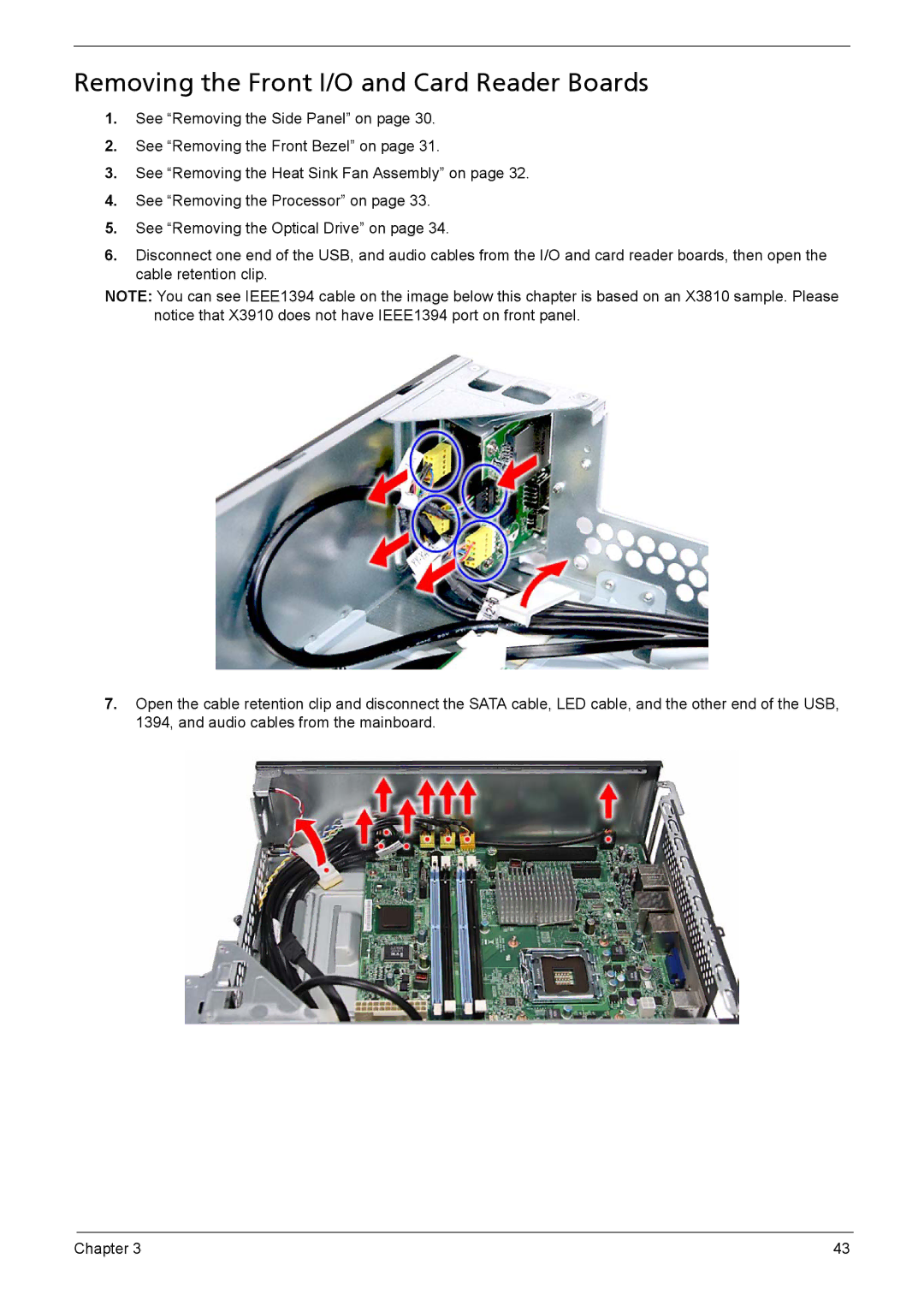
6.Disconnect one end of the USB, and audio cables from the I/O and card reader boards, then open the cable retention clip.
NOTE: You can see IEEE1394 cable on the image below this chapter is based on an X3810 sample. Please notice that X3910 does not have IEEE1394 port on front panel.
7.Open the cable retention clip and disconnect the SATA cable, LED cable, and the other end of the USB, 1394, and audio cables from the mainboard.
Chapter 3 | 43 |